Author Topic: VEC300 with 5kW motor  (Read 33664 times)

Offline Corchard

  • Confirmed
  • New Member
  • *
  • Posts: 12
Re: VEC300 with 5kW motor
« Reply #15 on: April 27, 2025, 02:51:29 PM »
Thank you for the quick response and thank you for the reminder on the upload tool tools' idiosyncrasies. 

I've got that one figured out:
  • connect to controller
  • save parameters to controller
  • power down controller
  • wait 30 seconds and power powercontroller
  • connect to controller and validate new values
I'll may try to activate the brake test however the reason I am reluctant to put a voltage meter any where near the throttle assembly in the live system is that I had a runaway that lasted <2 seconds that destroyed my Shaft coupling.  It's a wonderfully powerful motor.

I'll try with the settings you suggested.

As as safety feature I've purchased potentiometer with a  Detent at zero.   Here is the bench test profile:

Digikey potentiometer bench results:
PositionBlack–Red (O, V)Black–Green (O, V)Red–Green (O, V)
Idle (0%)0 O, 0.00 V10.00 kO, 0.00 V10.00 kO, 0.00 V
25%~2.5 kO, 1.25 V~7.5 kO, 1.25 V~5.0 kO, 3.75 V
50%~5.0 kO, 2.50 V~5.0 kO, 2.50 V~5.0 kO, 2.50 V
75%~7.5 kO, 3.75 V~2.5 kO, 3.75 V~7.5 kO, 1.25 V
Full (100%)10.00 kO, 5.00 V0 O, 5.00 V10.00 kO, 0.00 V

Any Way to make this work?

I really appreciate you taking the time to help us all out.


Offline Bikemad

  • Global Moderator
  • Professor
  • PhD. Magic
  • ******
  • Posts: 5,601
Re: VEC300 with 5kW motor
« Reply #16 on: April 28, 2025, 12:15:46 AM »
As as safety feature I've purchased potentiometer with a  Detent at zero.   Here is the bench test profile:

Digikey potentiometer bench results:
PositionBlack–Red (O, V)Black–Green (O, V)Red–Green (O, V)
Idle (0%)0 O, 0.00 V10.00 kO, 0.00 V10.00 kO, 0.00 V
25%~2.5 kO, 1.25 V~7.5 kO, 1.25 V~5.0 kO, 3.75 V
50%~5.0 kO, 2.50 V~5.0 kO, 2.50 V~5.0 kO, 2.50 V
75%~7.5 kO, 3.75 V~2.5 kO, 3.75 V~7.5 kO, 1.25 V
Full (100%)10.00 kO, 5.00 V0 O, 5.00 V10.00 kO, 0.00 V

Any Way to make this work?

Something doesn't look right with those readings, it looks as if you may have the wires incorrectly connected to the potentiometer pins because the resistance or voltage reading between the Red and Black should remain at 10kOhm or ~5V regardless of the position of the potentiometer's wiper.


"A" = Black (0V)    "W" = Green (Throttle signal)    "B" = Red (+5V)


Fitting resistors on the Red and Black wires as per the above diagram should allow that potentiometer to operate as a throttle.
According to my calculations, if you used a 2.4kOhm resistor on the Black (0V) wire (instead of the 1.5kOhm resistor shown above) this should produce a throttle signal output voltage of 0.83V to 4.31V with a 5V supply.

Alan
 

Offline Corchard

  • Confirmed
  • New Member
  • *
  • Posts: 12
Re: VEC300 with 5kW motor
« Reply #17 on: April 28, 2025, 12:47:44 AM »
Ugg sorry ... In copying to basic the HTML/BBC coding I got everything all messed up.

The profile for the Detent potentiometer follows the non-detent  one, except for the 0 position, which reads 0 Volts, 0 Ohms across the board.

Essentially is the 0 detent cutoff feature enablable in the controller or will the open circuit think that there is no throttle present?

Offline Bikemad

  • Global Moderator
  • Professor
  • PhD. Magic
  • ******
  • Posts: 5,601
Re: VEC300 with 5kW motor
« Reply #18 on: April 28, 2025, 11:49:17 AM »
Hi Charles, there is no "detent cutoff feature" that can be enabled in the controller.

If the detent potentiometer only has 3 pins it may not have a "cutoff" feature, the detent may purely be used to locate the shaft in a certain position without causing an open circuit.
Usually, if the detent also activates a ON/OFF switch, the switch mechanism and wiring is completely separated from the Resistance/Wiper pins as shown below:


If your potentiometer has 5 pins it should work fine if wired correctly.
If it only has 3 pins (and it definitely disconnects the resistance circuit) it should still be possible to use it, but it would require an additional 10k trimpot and a diode to also be connected to the three throttle wires to provide the expected idle position voltage on the Green throttle signal wire when the switch is in the OFF position.

Do you have a DigiKey part number or a link to the potentiometer/datasheet?

The profile for the Detent potentiometer follows the non-detent one, except for the 0 position, which reads 0 Volts, 0 Ohms across the board.

Zero Ohms and zero Volts would seem to indicate a short circuit rather than an open circuit, which is why I questioned your wiring connections. You might want to double check your connections and your results. ;)

Digikey potentiometer bench results:
PositionBlack–Red (O, V)Black–Green (O, V)Red–Green (O, V)
Idle (0%)0 O, 0.00 V10.00 kO, 0.00 V10.00 kO, 0.00 V
25%~2.5 kO, 1.25 V~7.5 kO, 1.25 V~5.0 kO, 3.75 V
50%~5.0 kO, 2.50 V~5.0 kO, 2.50 V~5.0 kO, 2.50 V
75%~7.5 kO, 3.75 V~2.5 kO, 3.75 V~7.5 kO, 1.25 V
Full (100%)10.00 kO, 5.00 V0 O, 5.00 V10.00 kO, 0.00 V

Some of the above results would make more sense if you had wired the potentiometer incorrectly as shown below:
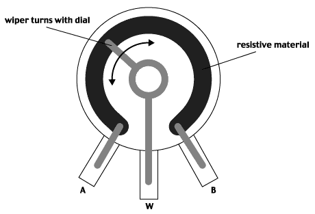
    "A" = Red (5V)    "W" = Black (0V)    "B" = Green (Throttle signal)  <---- This configuration is incorrect

Alan
 
« Last Edit: April 28, 2025, 11:59:55 AM by Bikemad »