Hi Abe,
If the voltage at the battery does not change when the yellow LED is on or off, it looks like you must be getting some voltage drop at the gauge when the key switch is operated. I have no way of knowing how your relays have been wired, but I suspect the power used to energise the two relay solenoids
(windings) may be affecting the gauge operation, which might also explain why the light comes on for a second after the key switch is turned off
(fed briefly by the residual battery voltage stored in the controller's capacitors).
Does the battery feed going to the key switch come directly from the battery power connector, or could the key switch feed wire
(or relay ground wire) be connected somewhere to the wiring harness itself?
If the key switch and relay solenoid
(windings) circuit is not on the battery side of the battery connector, it should be wired totally separate from the main wiring harness and should not utilise any of the thin harness wires to carry either the battery feed or the ground return. The relay and key switch wiring should connect directly to the battery power connector in parallel with the thick Red and Black battery power cables coming from the motor harness.
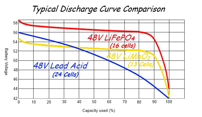
I'm pretty sure that having the 15 watts of lighting turned on will also affect the operation of the battery gauge as the ~270mA of current will definitely cause a slight voltage drop along the shared thin wires. The simple LED battery gauges were originally intended for use with lead acid batteries and are not much good for monitoring the higher voltage LiFePo
4 and LiPo batteries, so if you are very lucky, you might even find that having the lights on will reduce the voltage at the LED battery gauge enough to make it work more a little bit more realistically.

This basic LED battery gauge was originally designed for lead acid type batteries which have a more pronounced voltage drop throughout their discharge, but the LiFePO4 batteries in use today have a higher voltage which drops very little in comparison as they discharge, and the LEDs would probably remain fully lit for 90-95% of the battery's use.

Take a look at this post to find out how a resistor can be used to adjust the gauge operation to better suit the battery type being used. As your cable has already been chopped it should be relatively easy to solder a variable resistor into the battery gauge power supply wire.
Incidentally, 55V seems a little bit low for a fully charged LiFePO
4 battery, as I would have expected be nearer 56~58.4V
(dependant upon the set charger voltage).
LiFePo
4 batteries have a very similar discharge characteristics to LiPo, and my LiPo cells would have to be ~25% discharged to achieve the same percentage of voltage drop from fully charged.
I would expect my GM 48V LiFePO4 battery to take a few weeks before for the residual drain of the
BMS alone could cause it to drop from 58.4V to 55V.
I can at least put your mind at ease regarding your concerns about it being a problem with the internal controller. The controller could not cause the gauge problem unless it was very heavily loading the battery and causing the battery voltage to drop excessively, which it obviously isn't doing
(this has already been confirmed by the constant 54V voltage reading).
Alan