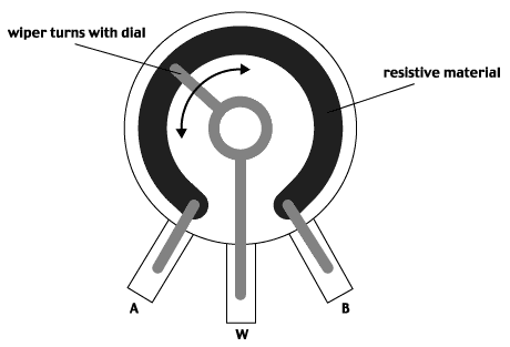
Hi Charles, there is no "detent cutoff feature" that can be enabled in the controller.
If the detent potentiometer only has 3 pins it may not have a "cutoff" feature, the detent may purely be used to locate the shaft in a certain position without causing an open circuit.
Usually, if the detent also activates a ON/OFF switch, the switch mechanism and wiring is completely separated from the Resistance/Wiper pins as shown below:

If your potentiometer has 5 pins it should work fine if wired correctly.
If it only has 3 pins
(and it definitely disconnects the resistance circuit) it should still be possible to use it, but it would require an additional 10k trimpot and a diode to also be connected to the three throttle wires to provide the expected idle position voltage on the Green throttle signal wire when the switch is in the OFF position.
Do you have a DigiKey part number or a link to the potentiometer/datasheet?
The profile for the Detent potentiometer follows the non-detent one, except for the 0 position, which reads 0 Volts, 0 Ohms across the board.
Zero Ohms and zero Volts would seem to indicate a short circuit rather than an open circuit, which is why I questioned your wiring connections. You might want to double check your connections and your results.

Digikey potentiometer bench results:
| Position | Black–Red (O, V) | Black–Green (O, V) | Red–Green (O, V) |
| Idle (0%) | 0 O, 0.00 V | 10.00 kO, 0.00 V | 10.00 kO, 0.00 V |
| 25% | ~2.5 kO, 1.25 V | ~7.5 kO, 1.25 V | ~5.0 kO, 3.75 V |
| 50% | ~5.0 kO, 2.50 V | ~5.0 kO, 2.50 V | ~5.0 kO, 2.50 V |
| 75% | ~7.5 kO, 3.75 V | ~2.5 kO, 3.75 V | ~7.5 kO, 1.25 V |
| Full (100%) | 10.00 kO, 5.00 V | 0 O, 5.00 V | 10.00 kO, 0.00 V |
Some of the above results would make more sense
if you had wired the potentiometer incorrectly as shown below:
 "A" = Red (5V) "W" = Black (0V) "B" = Green (Throttle signal) <---- This configuration is incorrectAlan