Author Topic: Magic Pie II Max Current?  (Read 11860 times)

Offline Ceylanm

  • Confirmed
  • New Member
  • *
  • Posts: 7
Magic Pie II Max Current?
« on: April 15, 2012, 11:05:57 AM »
Hi

I need help about Magic Pie II motor.

We have two MPII motors mounted to our electricle vehicle.
We are driving them at 48V.
At full torque (not let it to be go), maximum current which we measured is 20A
This current value is total for two of them. Also we have measured by one by and they are taking 10A seperately.

Power for one motor is calculated as 500W according to above measurements.
But it is seen, these motors have 1kW power.

So how could we drive them at 1kW?

Thanks

Offline Bikemad

  • Global Moderator
  • Professor
  • PhD. Magic
  • ******
  • Posts: 5,499
Re: Magic Pie II Max Current?
« Reply #1 on: April 15, 2012, 01:50:41 PM »
Hi Ceylanm andto the forum.

10 Amps each does seem to be a very low reading. If they are external controllers, it's possible that they may have been factory set at a lower current for use with the 250W mini motors but accidentally supplied with the Magic Pies.
If they are internal controllers, perhaps they might have been programmed to comply with EU and Australian regulations.

What power source were you using to test them with and how did you measure the current?
(Connected in-line or inductive clip on type ammeter)


Do you have the USB programming lead? If so, what are the controller settings?

Alan
 
« Last Edit: July 05, 2017, 06:00:30 PM by Bikemad »

Offline e-lmer

  • Technical Officer
  • Master of Magic
  • ******
  • Posts: 458
    • My page
Re: Magic Pie II Max Current?
« Reply #2 on: April 15, 2012, 06:30:43 PM »
The torque measured on a stopped wheel will be
Inconclusive.
The current is modulated by the hall sensors.
They need a changing flux to function.

Try measuring torque/power at a fixed speed
(eg tied to a moving car at 5mph)

Offline Bikemad

  • Global Moderator
  • Professor
  • PhD. Magic
  • ******
  • Posts: 5,499
Re: Stall torque
« Reply #3 on: April 16, 2012, 02:22:09 AM »
Elmer, the hall sensors tell the controller which windings to energise according to the position of the magnets, even when the wheel is stationary.

Maximum current draw (and Maximum torque) should occur when full throttle is applied with the wheel stationary. As soon as the wheel starts to move, the torque and current consumption should start to decrease, so at 5mph it should be less than the results measured at 0 mph.

To prove this, I carried out a stall torque test on my original MKI Magic Pie, using a set of digital luggage scales attached by a piece of rope tied to the outer diameter of my tyre as shown here:


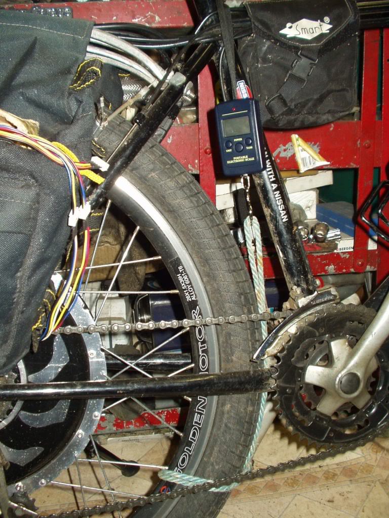
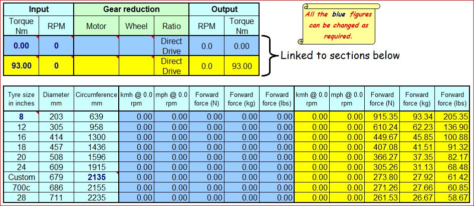
I opened the throttle fully, but the Pie would cut out every time before the scales could lock and retain the reading, but I was able to read at least 28kgs/61Lbs of force on a couple of the tests, and by entering the circumference of my 26" x 2.3" tyre into my spreadsheet I reckon that my stall torque is somewhere around 93Nm!


My Turnigy Watt Meter recorded a massive 65.94 Amps @ 25.6V (1,694 Watts) from my 25.9V 10Ah LiPo pack, which is the highest amperage I have recorded since I modified my controller almost 12 months ago, and this was with the wheel 100% stationary.

From my point of view, this test was pretty conclusive. ;)

Unfortunately, there is negative side to this test, I was so impressed with the results on the 25.9V pack that I decided to try it with double the voltage (51.8V 10Ah). So I connected another LiPo pack in series and proceeded to do the same test as before, but as I started to accelerate and the scales started to rise, the motor suddenly cut out, accompanied by the dreaded five beeps that usually indicate the death of the controller. :(

I instinctively disconnected and reconnected the battery to see if the controller would reset and work again (which it didn't) without realising that I was also disconnecting my watt meter at the same time, so I never got to see how high the power consumption was that caused the failure. ::)

To be perfectly honest, I'm amazed that this controller has actually lasted this long.  It's been nearly 12 months since the shunt was modified, and since then, it's been delivering almost 60 Amps on a regular basis.

Following the controller failure, the wheel was lumpy to turn so I quickly removed it and pulled it apart to perform a post mortem.
It would appear that just one of the MOSFETs has died, so I've just replaced it with one of the five remaining good ones taken from Ginge's dead controller that I blew up during my twin controller experiment 12 months ago.

Tomorrow I will put the wheel back together again and see if the controller still works, and if it does, I definitely won't be performing the stall torque test on the high voltage again.

I'll let you know whether it works again after I've reassembled and tested it.


Alan
 
« Last Edit: July 05, 2017, 05:55:53 PM by Bikemad »

Offline Bikemad

  • Global Moderator
  • Professor
  • PhD. Magic
  • ******
  • Posts: 5,499
Re: Controller failure update
« Reply #4 on: April 16, 2012, 02:36:50 PM »
Today I decided to plug the controller to a battery before I refitted it to the wheel and was relieved to only hear 4 beeps instead of Five! The Four beep is an indication of hall sensor failure, but as I discovered before, it also does this when there are no magnets near the hall sensors.

I then carried on and refitted the stator back into the wheel. I decided to check that the motor was turning freely before fitting the wheel back on the bike. I placed a 10mm spanner on the axle flats and was disappointed to find that the shuddering was still there, meaning that the stator had to be removed again to find the cause.

I rechecked the resistance between all six of the MOSFETs and each of the phase wires and could not find a problem. ???

I decided that the only other thing that would cause the juddering would be a short between two of the windings. I measured the resistance between all three windings and discovered a very low resistance between the blue and yellow phase wires. Assuming that the problem was somewhere in the windings, I unsoldered the phase leads from the controller and rechecked their resistances. All three sets of windings had the same resistance with no sign of a short, so I turned my attention to the controller.
When I checked the resistance between the three phase wire contacts, I confirmed that the short was between the blue and yellow contacts on the circuit board and not the windings.
I looked very closely between the tracks on the circuit board, but could not see anything amiss. I then unsoldered the two thick battery wires and removed the three screws holding the controller onto the heatsink and turned it over to inspect the other side.
I then noticed that some solder had somehow run across the gap between the blue and yellow tracks, this was quickly removed with the soldering iron and everything was reassembled and rechecked.

While it was still apart, I couldn't resist the temptation of adding a bit more solder to the additional shunt that I had added 12 months ago to see if I could boost the current just a little bit more.  :o

The reassembled wheel turned easily without any sign of juddering and did not beep when I tried connecting power, so I carried on and fitted the wheel.

I was very excited to find that my faithful Magic Pie was alive and kicking once again!


I couldn't wait to test it out so I went for a quick ride around the garden and tested it on the slope at the side of my house and it is now even better than before.
With the extra solder on the shunt, it now pulls over 72Amps from my 25.9V 10Ah LiPo pack, which gave a maximum recorded reading of 1833.7Watts!

With this level of current, my controller is definitely running on borrowed time, but for me, the performance is worth the risk!
Although I'm now a little bit concerned about running it on a 51.8V pack, but I think it may have to be done purely to satisfy my curiosity if nothing else.
                                           

Alan
 
« Last Edit: July 05, 2017, 05:54:53 PM by Bikemad »

Offline Bikemad

  • Global Moderator
  • Professor
  • PhD. Magic
  • ******
  • Posts: 5,499
Re: Magic Pie I Max Current is now even higher than last time
« Reply #5 on: April 19, 2012, 03:43:27 PM »
Today I went for a ride up to the local field and proceeded to give my modified Pie a pretty hard workout to see if it was likely to fail. This consisted of lot's of full throttle starting on inclines and plenty of wheelies (with just a little bit of pedal assistance) and I have to say that is was fantastic fun! ;D
I think my reactions must also be improving, because I didn't manage to flip it over backwards at all today! :D

I'm still thoroughly enjoying the increased power, and the Pie's original internal controller seems to be coping very well, which I feel is amazing, considering the extreme load it must be under.
I still haven't tried running on the high voltage pack (Not since the latest shunt modification) because I'm convinced that I will probably blow the controller again. :o

Here are the maximum current and power readings shown at the end of today's test session:

I think that 77Amps and almost 2kW of power is exceptionally good for a 25.9V Pack!

I'm really enjoying being a "test pilot" for this shunt mod and just hope my Magic Pie can cope with all the abuse that I'm currently subjecting it to for as long as possible.

I'm now seriously considering strapping another set of six MOSFETs to the spare heatsink inside my motor (where the second controller used to be) and simply connecting the battery +ve, Battery -ve, the three phase wires and six gate connections in parallel to the ones on my existing controller.

If I was to connect the battery -ve connection of the additional MOSFETs directly to the battery negative lead (instead of going though the shunt) it should at least double the power output (if my theory is correct), which I think might just be pushing the load on the battery wiring a little bit too far. ::)

I think it might be sensible to run the extra -ve wire through the existing shunts, which would allow the same power output that I currently have (or probably a bit more), but more importantly it would reduce the load on the MOSFETs by half! ;)
I would then have no hesitation about running on the higher voltage battery pack through the proposed 12 FET system.

My result so far have shown that the controller delivers slightly more Amps on the 51.8V pack than it does on the 25.9V pack, so I could therefore realistically expect the maximum power consumption to be >4kW. 8)

Alan
 
« Last Edit: July 05, 2017, 05:53:14 PM by Bikemad »

Offline Morgen 3Eman

  • Confirmed
  • PhD. Magic
  • ******
  • Posts: 620
Re: Magic Pie II Max Current?
« Reply #6 on: April 19, 2012, 05:09:42 PM »
Hi Alan,

I like your style.

The rope and luggage scale instrumentation is too cool for words, so I'm shutting up.

TTFN,
Dennis

Offline Ceylanm

  • Confirmed
  • New Member
  • *
  • Posts: 7
Re: Magic Pie II Max Current?
« Reply #7 on: April 20, 2012, 07:28:41 AM »
Thank you for your attention and given info about your trials.
That's all very informative.

I attached our motor settings to this message
We are using in-line ammeter, Eagle Tree eLogger v4.

Batteries are NiCd for now. But they could purge high currents. On the other hand, with two motor driving, we could see 20A at ammeter. We want to able to drive the motor at full torque with 48V / 20A as stated its spec sheet.

What do you suggest to increase the maximum current (torque) of motor?
For now, its 500W.
We need 1kW maximum.


« Last Edit: April 20, 2012, 11:38:02 AM by ceylanm »

Offline Bikemad

  • Global Moderator
  • Professor
  • PhD. Magic
  • ******
  • Posts: 5,499
Re: Magic Pie II Max Current?
« Reply #8 on: April 20, 2012, 12:56:06 PM »
The only easy thing I can suggest that might make a difference is to load the "Factory Settings" and then change the "Regen Brake" and "REVerse" settings to suit, but make sure you leave the "Motor Voltage" set to 24V, as there have been a few reported cases where this seems to produce more noticeable power.

The recently introduced "RPM" setting apparently affects how quickly the throttle responds, so try setting this to 100% and see if it makes any difference to your measured current figures.

If you can't increase the current to 20Amps using the software alone , you will either have to modify the shunt on the controller's circuit board, change a resistor on the circuit board or replace the controller.

Alan
 
 
« Last Edit: April 20, 2012, 12:57:55 PM by Bikemad »

Offline Bikemad

  • Global Moderator
  • Professor
  • PhD. Magic
  • ******
  • Posts: 5,499
Re: Magic Pie I Max Current is now much higher than last time
« Reply #9 on: April 24, 2012, 03:39:34 PM »
Here are the maximum current and power readings shown at the end of today's test session:

I think that 77Amps and almost 2kW of power is exceptionally good for a 25.9V Pack!

My result so far have shown that the controller delivers slightly more Amps on the 51.8V pack than it does on the 25.9V pack, so I could therefore realistically expect the maximum power consumption to be >4kW. 8)


Hey, guess what? I finally gave in to my curiosity and tried the motor on the higher voltage, and I was right about the predicted power output:


I now think that 97.75Amps and almost 4.4kW of power is even better for a 51.8V 5Ah Pack!

We've had a couple of days of rain here and the lane up to the field was very muddy making it impossible to pull away without wheel-spinning. When I reached the field, and had a bit more grip, the front wheel would lift up every time I pulled away on the flat (without pedalling) and pulling away on hills required a very gentle touch on the throttle.
On the higher voltage pack, I experienced some cutting out after brief acceleration and then closing the throttle. If I slowed down and tried to use the throttle again there was nothing until I operated the brakes, which seemed to reset it. Under heavy acceleration, I was aware of some beeping coming from the rear, but after seeing the minimum voltage reading of 45V on the Watt Meter, I'm now convinced it was just my battery warning device letting me know that the voltage was starting to get a bit low.

I also manage to do something I've never done before, I actually pulled a one handed wheelie!! ;D


I still haven't tried running on the high voltage pack (Not since the latest shunt modification) because I'm convinced that I will probably blow the controller again. :o

Unfortunately, this prediction also came true, my riding session finally ended abruptly with the dreaded 5 beeps of death from the controller, just as I went to wheelie up my driveway. :(
This time, there is no shuddering from the motor, which hopefully just indicates that the MOSFET that has blown has failed in the open circuit condition instead of being shorted out, so I could still have pedalled home if I'd needed to.

I think another post mortem is now required to find out if it's a simple matter of replacing another MOSFET, or whether the 97+ Amps has caused more extensive damage to the controller itself. ::)

I'll let you know what I find. ;)

Alan
 
« Last Edit: July 04, 2017, 10:07:04 PM by Bikemad »

Offline Bikemad

  • Global Moderator
  • Professor
  • PhD. Magic
  • ******
  • Posts: 5,499
Re: Update on the blown controller
« Reply #10 on: June 06, 2012, 01:13:31 AM »

Here's the update to this thread with my findings on the blown controller.

Unfortunately, all six of the MOSFETs checked out OK, and I could not see anything else obvious on the circuit board that would indicate a failed component. All the measured voltages appear to be normal and the Hall Sensors are all working correctly too, so it seems as if one of the surface mount components may have failed internally, and I am not able to locate where the failure is, so it looks like I am going to have to replace the whole controller this time.

I still think that doubling up on the MOSFETs on a good controller will provide double the power without overloading the controller, and when I get a chance to put this theory to the test I will update this thread with my findings, but it is not likely to be in the immediate future due to other more important work that needs to be done on the house.

I am currently using an MPII with a slightly modified shunt which is drawing almost 50 Amps from my 25.9V LiPo pack, but I'm now even more reluctant to run it at the higher voltage, and I'm now having to accept the fact that 1.33 kilowatts is just not as much fun as 4.39 kilowatts! ;)

Alan
 

Offline Morgen 3Eman

  • Confirmed
  • PhD. Magic
  • ******
  • Posts: 620
Re: Magic Pie II Max Current?
« Reply #11 on: June 06, 2012, 03:44:58 AM »
I am impressed!  I'm also surprised that the motor windings are surviving 100 Amps!  I've only seen photos of the windings, but they don't look big enough to routinely handle that current . 

Repeat after me:  "I don't wanna grow up, I'm a Toys-R-Us kid!"  Keep having fun.

TTFN,
Dennis

Offline jan-norway

  • Confirmed
  • New Member
  • *
  • Posts: 17
  • I have a Prokit 901
Re: Magic Pie II Max Current?
« Reply #12 on: June 07, 2012, 06:03:10 PM »
I had alot fun reading this. Would like to test 4kw too:)