Author Topic: Club Car with 10kw and 500A controller. Only 21mph??  (Read 23306 times)

Offline Apcerame

  • Confirmed
  • New Member
  • *
  • Posts: 5
Club Car with 10kw and 500A controller. Only 21mph??
« on: May 18, 2020, 04:55:51 PM »
Attempting to dive into a friends golf cart.  He purchased a 48V 10kW motor and a VEC500 controller.  The cart runs good, a little jerky, but maxs out at 21 mph. 

Looking at the motor specs, the motor should turn up to 6000 rpm. 

I know speed will depend on gearing/wheel size.  But is there anyway to check motor rpm?  Like reading the position sensor of the motor with a dmm? 

I’ve dug a little into the programming, is there any settings I should look at?  What’s the max rpm the VEC500 can do? 


Offline Bikemad

  • Global Moderator
  • Professor
  • PhD. Magic
  • ******
  • Posts: 5,553
Re: Club Car with 10kw and 500A controller. Only 21mph??
« Reply #1 on: May 18, 2020, 09:07:36 PM »
Hi andto the forum.

According to the dynamometer test data for the 10kW motor on 48v, it is only rated for 10kW@3,500rpm and the maximum recorded speed under minimal load appears to be 4,733rpm.

The GM 10kW motor can only produce 10kW of power at motor speeds up to ~3,515rpm, above this rpm, the maximum available power will gradually drop off.

If you look at the motor test curve you can see that the power output (Pout[W]) only increases as the rpm (N[rpm]) reduce.

Below 3,500rpm, the battery and/or controller's current limitation will determine the maximum power.
Your battery and controller would need to be able to supply at least 270 Amps to achieve a power output of 10kW, but the VEC500-48 controller appears to have a 200A maximum current rating. ???

Looking at the Dyno figures, I estimate that 200A would produce a maximum output of ~8.05kW@3790rpm.

If you want to gear it for maximum speed, and don't want it to climb hills, you will need to ensure that the rpm is ~3750 at the calculated maximum speed to enable the full 8.05kW of power to be available at this speed on the level.

However, if maximum hill climbing speed is more important, then you will need to reduce the gearing to suit the calculated maximum speed that 8.05kW of power can propel the vehicle up the maximum anticipated incline.

If more power is required at lower speeds for quicker acceleration (and the batteries are able to supply the required current) you would need to use dual VEC500-48 controllers (one for each of the two phase wire/Hall sensor sets).

Alan
 

Offline Apcerame

  • Confirmed
  • New Member
  • *
  • Posts: 5
Re: Club Car with 10kw and 500A controller. Only 21mph??
« Reply #2 on: May 19, 2020, 05:32:10 PM »
Hey Alan, thanks for the detailed response. 

So if you don’t mind, I’m going to keep asking questions. 

I understand AC motor theory and rpm being mainly based on frequency.  I understand Rpm in DC motors is from voltage.  And both on other factors engineered into the motor.  I’m also familiar with VFDs on AC motors. 

So in my head I’m thinking a brushless dc motor controller works a lot like a VFD, in that it is cycling/pulsing the stator currents.  So the faster the pulses, the faster the motor spins. 

Is this thought right?  Thanks, Anthony.

Offline Bikemad

  • Global Moderator
  • Professor
  • PhD. Magic
  • ******
  • Posts: 5,553
Re: Club Car with 10kw and 500A controller. Only 21mph??
« Reply #3 on: May 19, 2020, 10:48:29 PM »
Hi Anthony,

Here's my interpretation, I think PWM is used to control the current and the three Hall sensors embedded in the stator simply control the switching of the individual phases relative to the position of the magnets on the rotor.
Although it may be possible to electronically alter the motor timing to some extent, the actual speed at which the switching occurs will always be directly linked to the rpm of the motor shaft/rotor, because if it was switched any faster (or any slower) the motor timing would instantly be lost.

The maximum unloaded speed of the motor will ultimately be governed by the battery voltage, and the rpm/volts ratio will be determined by the number of turns and the thickness of copper wire used for the stator coil windings.

At speeds below the motor's maximum rpm, the torque and/or speed can be controlled by adjusting the average current (and presumably the average voltage too) by using PWM control.

Here is my representation of a very simple MOSFET power circuit that could be used to control the DC phase switching if the MOSFETS were directly controlled by three Hall sensors.
Please Note: The Hall sensors and additional circuitry is not shown, this was done to keep the power circuit diagram as simple as possible:
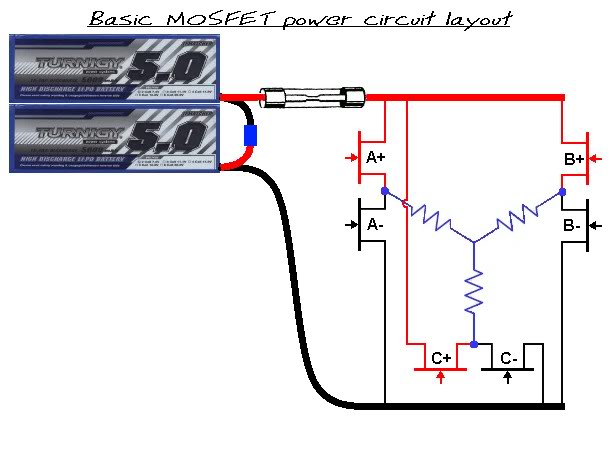


If the Hall sensors switched the MOSFETS either 100% High or 100% low with no PWM control whatsoever, they would effectively function as an electronic commutator, and the motor would simply run at maximum power/speed from the fixed voltage battery.
However, if the fixed voltage battery was replaced by a variable voltage power supply, the power/speed of the motor could then be controlled by varying the supply voltage just like you can with a conventional brushed motor.

From my point of view, a DC brushless motor basically works in a similar fashion to a simple DC brushed motor except that it uses sensors and electronic components to switch the polarity of the windings instead of a mechanical commutator, and I'm pretty sure that the unloaded speed of both motors will still be directly proportional to the voltage being supplied.

Having said all of the above, my understanding of how a BLDC motors and controllers work is still quite basic  ::) so please feel free to correct me if I've got it all completely wrong.  :-[

Alan
 

Offline TheKing

  • Confirmed
  • Junior Member
  • **
  • Posts: 28
Club Car with 10kw and 500A controller
« Reply #4 on: June 08, 2020, 10:11:19 PM »
Hi Bikemad
I hope you find the time to look at my case. I'm writing to you for the second time, the first time I had a burn controller ... so I had to buy a new one
I converted Daewoo Matiz from 620 kg weight .... with 10 KW BLDC Motor, 500A Controller  from GM.
I put 4 155Ah lead batteries running on 48V
The vehicle works well on a flat road and on a downhill ... the problem occurs when I accelerate on low or higher uphill (or maintain speed) .... happens that the engine suddenly loses power (the controller shows flash off LED) but if I start driving again from the beginning the vehicle is running normally. Of course I lose the uphill speed and that is very inconvenient in regular traffic. Your opinion?

?hank you in advance
Jovan

Offline Bikemad

  • Global Moderator
  • Professor
  • PhD. Magic
  • ******
  • Posts: 5,553
Re: Club Car with 10kw and 500A controller. Only 21mph??
« Reply #5 on: June 09, 2020, 10:51:43 AM »
Hi Jovan,

Is the motor driving through the original gearbox/final drive unit?
If so are you using low gears at slow speed and on hills?

If my rough calculations are correct, the 29Nm of motor torque being produced at the rated 10kW output would require a total gear reduction ratio of ~11:1 to climb a 10 degree slope, and this should achieve a maximum of ~18mph (~30km/h) at 3500rpm with a 500mm diameter tyre.

I initially thought it might be temperature related, but from what you have said, it appears to reset too quickly for a temperature related problem.
I therefore suspect that the batteries might be overloaded under high current draw causing a large voltage drop, which is causing the controller to reduce the power going to the motor in order to prevent the battery voltage from being pulled too low.

Do you have a voltmeter connected to see exactly how low the battery voltage drops under heavy load?

Perhaps the 10kW of power and 29Nm of torque is just not enough for a 620kg vehicle, considering that the original petrol engine produced 38 kW and 69 Nm of torque.
Just as a comparison, the Vectrix VX-1 scooter weighs 210kg and its motor can produce up to 35kW of peak power and 65Nm of torque. It has a single fixed 3:1 gear reduction and has no problem accelerating at low speeds or climbing hills.

Alan


Offline TheKing

  • Confirmed
  • Junior Member
  • **
  • Posts: 28
Re: Club Car with 10kw and 500A controller
« Reply #6 on: June 10, 2020, 04:07:37 PM »
Hi Alan,
I'm sorry for the delay in answering. Let me tell you more about my problem.
Yes, I use the original Daewoo Matiz gearbox where the first gear has a 4.15: 1 ratio and is very slow for the uphills in my city and I use the second gear more often.
You have correctly concluded that temperature is not the cause because it's happen on cold controller and motor.
By the way, my intention is to use my vehicle for city traffic, my city has 40,000 inhabitants, so in a radius of 3 km I have everything I need and I am satisfied with the range of the vehicle of min 30 km. I only have a problem with losing power, speed its not priority.

I plan to connect a voltmeter tonight or tomorrow to see how the vehicle behaves under load.

I wondered, maybe I should change something in the parameters? .... so if you can look at * .foc file my last parameters that were entered through the USB cable ...
Regards
« Last Edit: June 10, 2020, 05:43:35 PM by TheKing »

Offline Bikemad

  • Global Moderator
  • Professor
  • PhD. Magic
  • ******
  • Posts: 5,553
Re: Club Car with 10kw and 500A controller. Only 21mph??
« Reply #7 on: June 10, 2020, 05:35:22 PM »
If you can attach the .foc file (don't use a "*" in the filename  ;)) I'll see if I can spot anything obvious that might be advantagous to change, but measuring the voltage under load will hopefully help to pinpoint the cause of the mysterious power loss.

Alan
 

Offline TheKing

  • Confirmed
  • Junior Member
  • **
  • Posts: 28
Re: Club Car with 10kw and 500A controller
« Reply #8 on: June 11, 2020, 07:38:48 AM »
Good morning Alan,

I just finished testing the vehicle by measuring the voltage under load ... and that's what we expected .... I started with 100% full batteries (51.6 V), and under higher load the voltage drops to ~42v and then loses strength. I looked at the app, "low voltage protection value" cannot be changed, it is determined, so I think I need to change something around the current ...! I hope there is a solution ...
Otherwise, like info, use batteries as in the picture, a model underlined in green.
Regards,

Offline TheKing

  • Confirmed
  • Junior Member
  • **
  • Posts: 28
Re: Club Car with 10kw and 500A controller. Only 21mph??
« Reply #9 on: June 11, 2020, 10:00:07 AM »
 Again looked at the app, "low voltage protection value" CAN be changed .... and I put now on 39 v and everything is fine now  .... my test is positive, on uphill voltage drop to 40.6 v but not lose power ....
Thanks for support and advice ...
Regards,

Offline Bikemad

  • Global Moderator
  • Professor
  • PhD. Magic
  • ******
  • Posts: 5,553
Re: Club Car with 10kw and 500A controller. Only 21mph??
« Reply #10 on: June 11, 2020, 12:37:25 PM »
Hi Jovan,

It's good to hear that you've been able to confirm my suspicions and better still, you've found a solution that seems to work.

The 10kW motor is obviously placing quite a large load on those batteries under high current conditions, let's hope that it won't be too much for them to cope with long-term.

I haven't had a chance to study your settings yet, but I will try to look at them later when I've got a bit more time to spare.

Alan
 

Offline TheKing

  • Confirmed
  • Junior Member
  • **
  • Posts: 28
Re: Club Car with 10kw and 500A controller. Only 21mph??
« Reply #11 on: June 12, 2020, 06:05:38 AM »
Hope to here you soon ...

Offline Bikemad

  • Global Moderator
  • Professor
  • PhD. Magic
  • ******
  • Posts: 5,553
Re: Controller parameter suggestions
« Reply #12 on: June 12, 2020, 05:35:17 PM »
Hi Jovan,

Here are some suggested settings that you might want to consider:

  • Increase the Rated motor speed (rpm) to 4500 for higher speeds in low gears.
  • Enable the Low voltage protection and set the Low voltage triggering current (V) to 42V.
  • Enable the Clear undervoltage state while throttle off.
    This should automatically reactivate the controller by releasing the throttle after a low voltage cutout has been triggered, allowing you to proceed using a lighter right foot to get home again.
  • Reduce the Battery drawn current should help to reduce the voltage sag under load.
  • Enable the Motor overtemperature protection to prevent the motor from being overheated.
  • increase the stall protection time to give it a bit more time to pull away on hills without cutting the power to the motor.
  • Enable the Throttle voltage range protection but make sure your throttle signal voltage is within the minimum and maximum valid voltage range.
    This is a particularly important safety feature that should prevent the motor from going to full throttle if the throttle ground wire breaks.  :o
  • Enable EBS to allow regenerative braking to put some power back into the batteries.
    You may have to reduce the Reverse charging current (A) to suit your batteries maximum charging current.
  • I presume the EBS Auto_Mode allows one pedal driving in a fixed gear, but probably no point enabling this if you have to change gear often.
  • Reducing the Boost Current (A) will help to reduce the voltage sag under heavy load.

I hope some of this is useful.

Alan


Offline TheKing

  • Confirmed
  • Junior Member
  • **
  • Posts: 28
Re: Club Car with 10kw and 500A controller. Only 21mph??
« Reply #13 on: June 22, 2020, 09:37:36 PM »
sory for late
I put your settings  in my controller but when I test car
I have not full power, only limited.
I notice that voltage in my battery going down to 46,47 V and stay on that value ... not drop down 40-43 V under load like before
Returning old values I have same good power
I don't know why but step by step I 'll find why its happen

Regards

Offline Bikemad

  • Global Moderator
  • Professor
  • PhD. Magic
  • ******
  • Posts: 5,553
Re: Club Car with 10kw and 500A controller. Only 21mph??
« Reply #14 on: June 22, 2020, 10:17:24 PM »
The power (and voltage sag) is directly related to the battery current, so it sounds like the current may have been reduced a little bit too far.

I think the Battery drawn current and Boost Current (A) will need to be increased until you find the best compromise between reduced power and reduced voltage sag.  :-\

How many Amps did you reduced each of them by?

Alan