Author Topic: Looking for Magic Pie wiring diagram  (Read 5504 times)

Offline Wazza

  • Confirmed
  • New Member
  • *
  • Posts: 1
Looking for Magic Pie wiring diagram
« on: June 28, 2019, 01:56:51 PM »
Hi I am just starting out a new business venture repairing and selling on Ebikes and hiring them out as I live just above the Camel Trail in Bodmin Cornwall. I have a magic 1000watt front wheel but wires cut right back so after a wiring diagram from wheel to bike please.
Kind regards
Warren
ReCycling ? Cornwall

Offline Bikemad

  • Global Moderator
  • Professor
  • PhD. Magic
  • ******
  • Posts: 5,495
Re: Looking for Magic Pie wiring diagram
« Reply #1 on: June 28, 2019, 05:47:35 PM »
Hi Warren andto the forum.

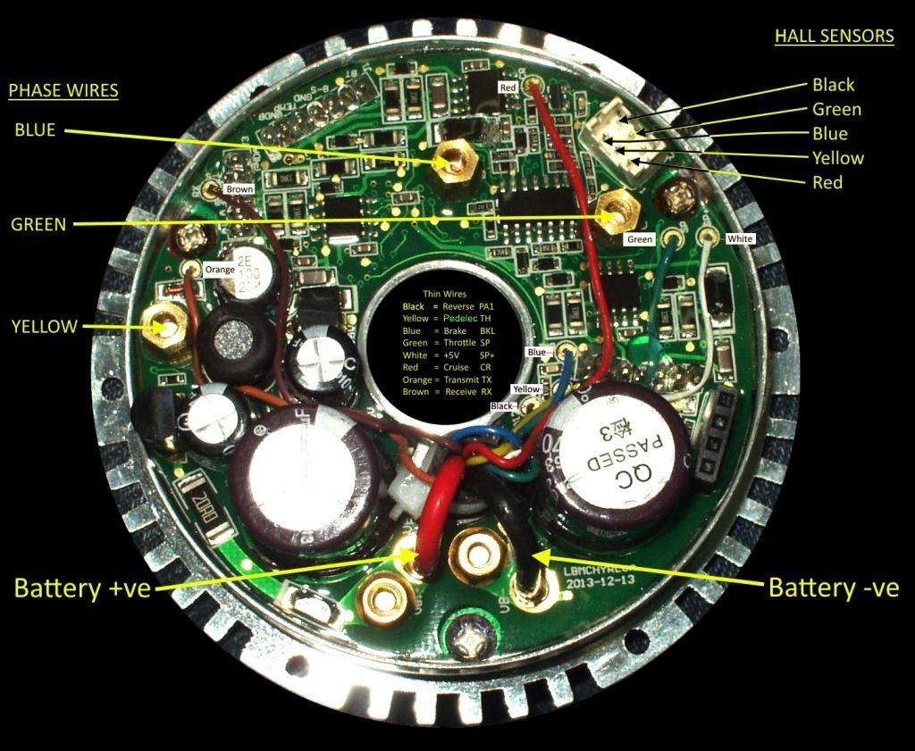
The very first Magic Pies (MPI and MPII) had their controllers completely hidden inside the motor:


The "unused" yellow wire was used for reverse and programming data on some controllers.

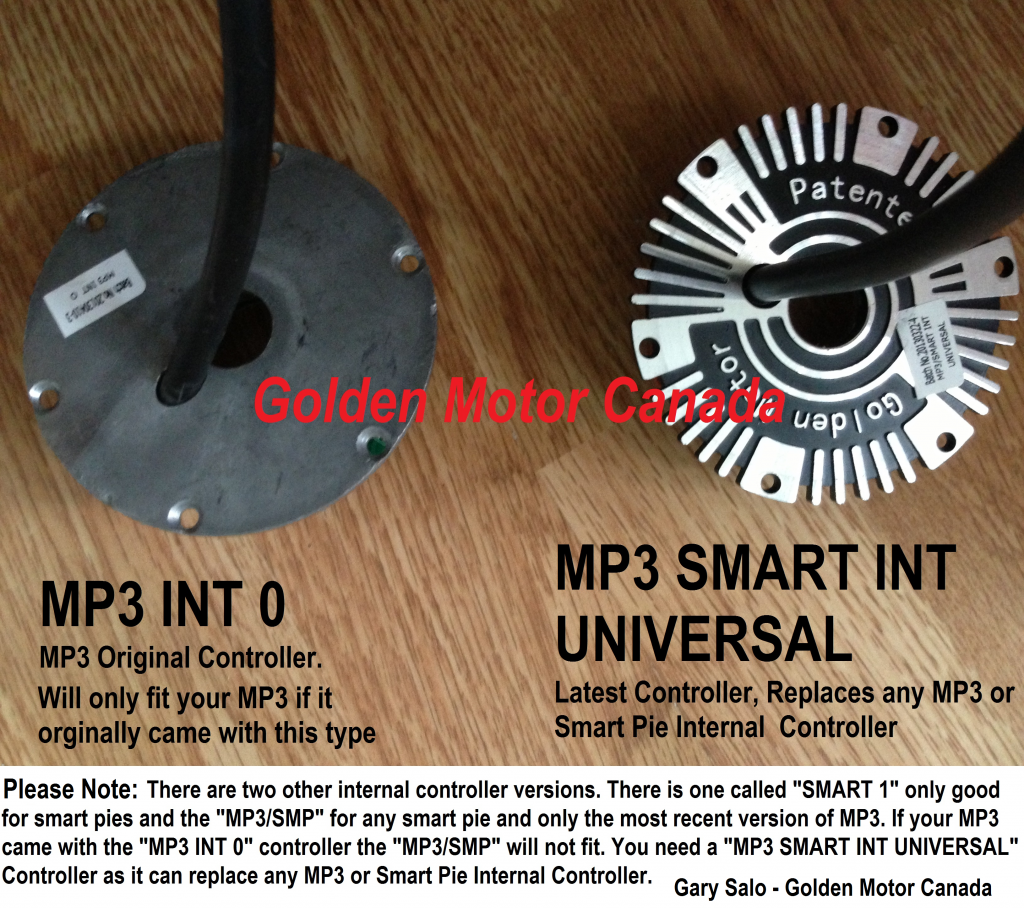
On the MPIII, MP4 and MP5, the controller is accessible from outside, as the cover of the controller is exposed to cooling air.

Early MPIII controllers had a plain cover as shown on the left, but later controllers (Late MPIII onwards) had cast cooling fin covers as shown on the right:


Here are the wiring diagrams for the harness connectors:


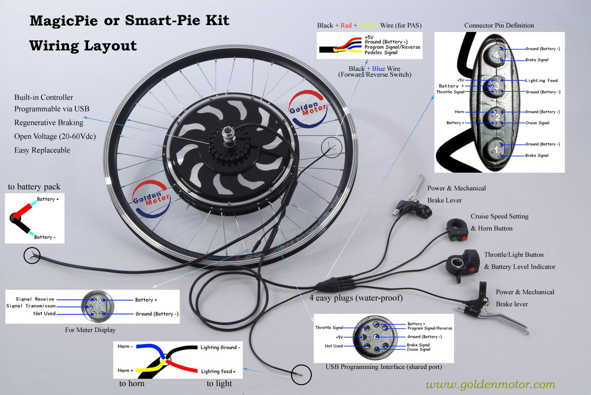
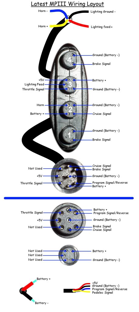
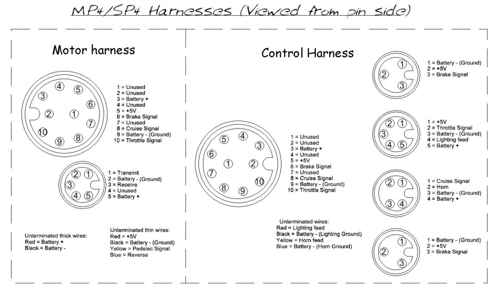
If it's a recent Magic Pie the connections will be like this:


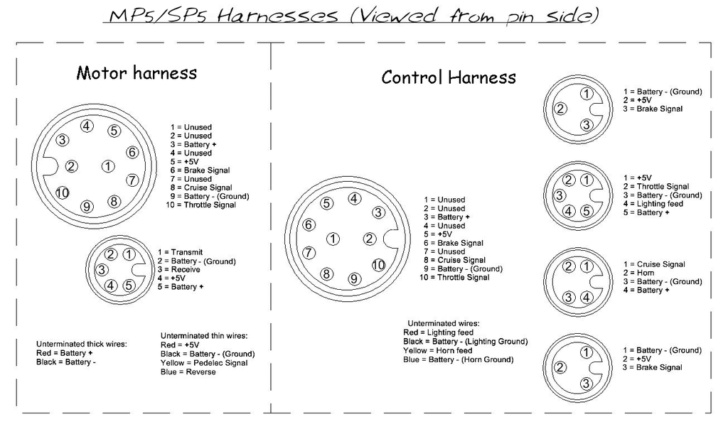
Hopefully this is enough information for you to figure out what each of the wires are for, but please ask if you need more details.

Alan
 

Offline MrFred

  • Confirmed
  • New Member
  • *
  • Posts: 21
Re: Looking for Magic Pie wiring diagram
« Reply #2 on: June 30, 2019, 12:43:24 AM »
This may be a dumb question, but I have an MP Edge with throttle-only - no PAS, no display. If I were to get the display (or the bluetooth dongle) where on that wiring diagram would that connect?

Offline Tommycat

  • Confirmed
  • Bachelor of Magic
  • ****
  • Posts: 178
Re: Looking for Magic Pie wiring diagram
« Reply #3 on: June 30, 2019, 01:05:11 PM »
See my completed Magic Pie V5 rear hub E-Bike build  HERE.

Offline Malo87

  • Confirmed
  • New Member
  • *
  • Posts: 10
Re: Looking for Magic Pie wiring diagram
« Reply #4 on: July 20, 2019, 10:39:17 PM »
HI there, what PAS sensor shall be used with the system? and for the light, would any 12v LED do?

Offline Bikemad

  • Global Moderator
  • Professor
  • PhD. Magic
  • ******
  • Posts: 5,495
Re: Looking for Magic Pie wiring diagram
« Reply #5 on: July 22, 2019, 12:59:09 PM »
The GM controllers require a "pulse mode" PAS Sensor for the PAS input signal.

Regarding the light, the voltage supplied to the light is full battery voltage, so your LED lamp must be suitable for your particular battery voltage (24V, 36V or 48V).

There are plenty of 12-80V LED lights available that will work with 24V, 36V or 48V (51.8V/52.8V) batteries, but I would suggest a maximum combined power output of 10~12 Watts.

Alan
 
« Last Edit: July 23, 2019, 12:11:43 AM by Bikemad »