Hi and

to the forum.
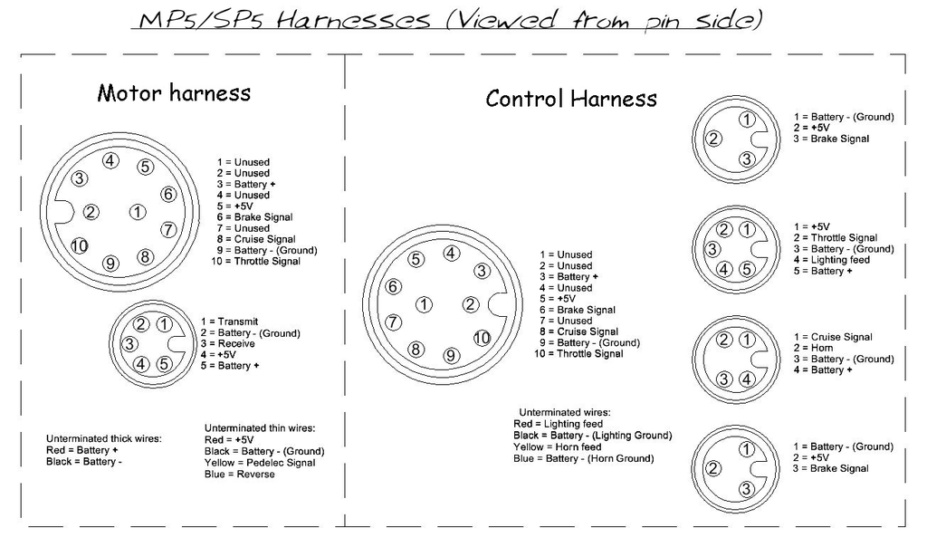
On the lower left hand side of the following diagram, you can see the pin allocations for the five pin connector on the Motor harness that is used for the Bluetooth, USB and the Smart LCD Display:

As pin 5 is supplied with battery voltage, if you had inadvertently bridged pins 4 and 5 with the meter probe while measuring the voltages, there's a possibility that some of the controller's electronic components
(and perhaps the Hall sensors in the motor, throttle, and Pedelec sensor too) may have been damaged by full battery voltage being momentarily applied to the +5V circuit.

This might also explain why the motor is no longer working.

However, I still don't understand why
"every pin was reading somewhere between 48-52v", as the voltage at pin 2
(the ground connection) should still be reading ~0V.
Incidentally, a battery pack voltage of 48-52V seems quite low for a 14S pack, as this equates to an average voltage of just 3.43-3.71V per cell.
Alan