Author Topic: Inside of my GM 48V 10Ah pack  (Read 10872 times)

Offline Zerogee

  • Confirmed
  • New Member
  • *
  • Posts: 15
Inside of my GM 48V 10Ah pack
« on: March 23, 2016, 06:06:27 AM »
I bought the battery in late 2014 and finally getting around to spitting the pack. It looks well put together and fits inside the aluminum housing like a glove. Not shrink wrapped instead covered on all sides with a sheet of G10 held on with double sided tape. Cells are cover in a foil. The cells are spot welded together with metal bus strips and  taped together with packing tape. No threaded studs. The main wires are sleeved. The sense wires are neatly organized and seperated. Very small enclosed BMS. Here's a look inside...


Offline Zerogee

  • Confirmed
  • New Member
  • *
  • Posts: 15
Re: Inside of my GM 48V 10Ah pack
« Reply #1 on: March 23, 2016, 06:08:34 AM »
More...


Offline Zerogee

  • Confirmed
  • New Member
  • *
  • Posts: 15
Re: Inside of my GM 48V 10Ah pack
« Reply #2 on: March 25, 2016, 01:42:18 AM »
Good opportunity to check cell voltages at this time. Cells are well balanced. 8)

Offline Mgizen

  • Confirmed
  • Junior Member
  • **
  • Posts: 36
Re: Inside of my GM 48V 10Ah pack
« Reply #3 on: March 25, 2016, 02:56:15 AM »
when does the golden motor 48v 10ah bms balance cells?

Offline Zerogee

  • Confirmed
  • New Member
  • *
  • Posts: 15
Re: Inside of my GM 48V 10Ah pack
« Reply #4 on: March 25, 2016, 04:40:18 AM »
Sorry, no idea when balancing is performed with this BMS. No idea how to check for that.

Also this BMS does not look anything like the ones that GM Canada carries.

Offline Bikemad

  • Global Moderator
  • Professor
  • PhD. Magic
  • ******
  • Posts: 5,553
Re: Cell Balancing
« Reply #5 on: March 28, 2016, 12:10:33 PM »
when does the golden motor 48v 10ah bms balance cells?

Without monitoring the individual cell voltages throughout the charging process it is difficult to say for sure how the GM BMS achieves cell balancing, but most similar BMS units will typically start to balance the individual cells only when the battery is almost fully charged.

The most common balancing procedure basically involves loading each individual cell when it reaches the target maximum voltage to simply "bleed off" the excess charging current to prevent further voltage increase within the cell. This simple process is designed to prevent the stronger individual cells from being overcharged whilst still allowing the weaker cells to absorb all of the available charge current, allowing their voltages to gradually increase (ideally to the same individual target voltage.)

My GM 48V 10Ah battery is constructed using 16 individual LiFePO4 cells with a fully charged target voltage of 3.65V per cell, therefore the charger needs to supply a maximum regulated voltage output of 58.4V (16 x 3.65V = 58.4V).

As cell balancing is typically performed at the very end of the charge process, it will usually balance the cells more evenly if the battery is left on charge for a while after the green light comes on, rather than switching the charger off straight away.

Fine balancing of unbalanced cells can often take a while to achieve, as it takes a lot longer to increase the voltage of weaker cells with the very low charging current that is typically supplied near the completion of the charging cycle.
This is why I often leave my battery on charge for at least 2-3 hours after the green light comes on to allow additional time for better balancing.

Alan
 

Offline Mgizen

  • Confirmed
  • Junior Member
  • **
  • Posts: 36
Re: Inside of my GM 48V 10Ah pack
« Reply #6 on: March 29, 2016, 03:47:33 AM »
Thanks Alan for the input. Seems logical.

Offline Zerogee

  • Confirmed
  • New Member
  • *
  • Posts: 15
Re: Inside of my GM 48V 10Ah pack
« Reply #7 on: April 05, 2016, 09:59:42 PM »
wasn't sure if I could open the BMS or if things would fall apart on the inside with some of those screws. I can't see the other side. The heatsink is bonded to the FETs.

Offline Craglett

  • Confirmed
  • New Member
  • *
  • Posts: 6
Re: Inside of my GM 48V 10Ah pack
« Reply #8 on: July 06, 2016, 05:26:32 PM »
Newbie question if you don't mind. I have the same battery and am guessing one or more of my cells have degraded because the power will suddenly drop out after about 15 miles (I usually get far more  and a gradual drop shown on the LEDs). Would someone kindly illustrate on one of these photos where to place the +/- probes of a multi-meter - or describe it of it's easy enough to understand.

Thank you.

Offline Bikemad

  • Global Moderator
  • Professor
  • PhD. Magic
  • ******
  • Posts: 5,553
Re: Inside of my GM 48V 10Ah pack
« Reply #9 on: July 06, 2016, 07:17:09 PM »
If you have access to the BMS, you can check the voltage of the individual cells (or cell groups on earlier LiMn batteries) by measuring the voltages on the balance lead connections as shown here:


Unfortunately, a weak cell may only show a low voltage relative to the others when it is actually under load. :(

To check the battery under load you will need to attach a suitable resistive load across the output terminals.

A 240V kettle or electric iron will draw less than 2.5 Amps @ 48V, and this might not be enough to show the weak cell.

Four 60W car headlamp bulbs connected in series should draw around 5 or 6 Amps but will get very hot!

Heating elements from an old cooker hob might be another option as you can switch them all on together to put more load on the battery.

An old electric bar type heater should work well, but a fan heater with an electric fan might get a bit too warm as the fan may not run on a DC battery.

If you wire the plug lead from a four way extension socket direct to you battery output connector you could plug in a combination of the above mains powered items (kettle, iron and bar heater etc.) but if they are 110V  instead of 240V be careful not to exceed the current rating of the mains cable or it could get hot enough to melt internally.  :o

Alan
 
« Last Edit: July 02, 2017, 04:36:22 PM by Bikemad »

Offline Craglett

  • Confirmed
  • New Member
  • *
  • Posts: 6
Re: Inside of my GM 48V 10Ah pack
« Reply #10 on: July 07, 2016, 07:59:21 AM »
What a brilliant and helpful reply. This is exactly what I needed to get me started.

Should the multi-meter be reading somewhere around 3.4v for a healthy fully charged cell when testing each of those groups?

Offline Bikemad

  • Global Moderator
  • Professor
  • PhD. Magic
  • ******
  • Posts: 5,553
Re: Inside of my GM 48V 10Ah pack
« Reply #11 on: July 07, 2016, 10:20:30 AM »
A fully charged LiFePO4 rectangular cell should read 3.6~3.65V per cell, a fully charged LiMn cylindrical cell (or LiPo) should read 4.1~4.2V per cell.

Be very careful not to touch the meter probes together (or bridge two adjacent contacts with a single probe) while touching the pairs of contacts, as you will get some nice big sparks and also risk melting the two connected balance wires.  :o

You can use a couple of short pieces of cable insulation or heat shrink tube (or make one from insulation tape) slid onto the end of each of the probes to stop the tip of the probe from slipping off the soldered pins.

The balance wire connector must be plugged into the BMS if the voltage checks are performed on the BMS contacts.

Alternatively, you can unplug the balance lead from the BMS and measure the voltages directly on the balance lead connector instead of the BMS.
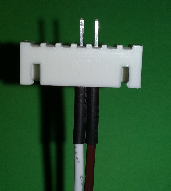


I use a modified LiPo balance lead connector (pictured above) which plugs directly into adjacent pairs of contacts on the battery's balance lead connector to avoid fiddling around with meter probes.
It makes it a lot easier to read the meter and record the voltages without having to keep an eye on the meter probes at the same time, or lose track of which cell you were checking previously. ;)

If you have one of these LiPo battery checkers:


You can simply plug it into the connector and measure up to 8 cells at a time and then move it along the connector to check the remaining cells.  :)

Alan
 
« Last Edit: July 02, 2017, 04:36:02 PM by Bikemad »