There are no on/off low power wires feeding the controller as the thick battery wires go direct to the motor controller circuit board and there is no practical way of isolating either the +12V supply used for switching the FETs, or the +5V supply for the Hall sensors in the motor, throttle and pedelec sensor, both of which are integrated into the main controller PCB itself.
While the battery is connected and turned on, the circuit board will be continually powered up and drawing a small amount of current. You will also have a battery voltage supply going directly to the throttle unit in order to supply the LED battery gauge, which will also remain lit and drawing a small amount of current while the battery is connected.
As suggested earlier by NR, you can switch the +5V supply going to the throttle in order to disable the motor power, but the controller will remain powered up and the battery gauge LEDs will remain illuminated.
On one of my bikes, I wired the light switch on the throttle to activate the regenerative brake when it was pressed in, and this prevents any unwanted motor activity if the throttle is accidentally operated while manoeuvring the bike etc.
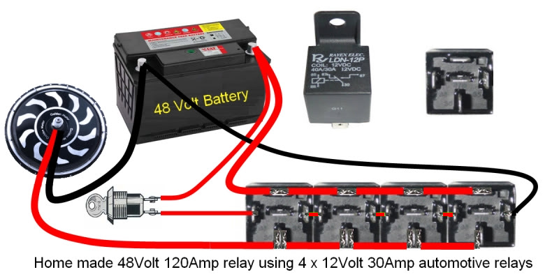
One way to incorporate a low current power switch (or two) near the handlebars would be to install a separate battery feed to operate a high current relay connected to the battery wires:

Alternatively, instead of using four 12V relays wired in series with paralleled contacts as shown above, you could install
a single 48V 40A relay or a
step down DC/DC converter with its output set to 12V to power a single
12V 40A relay:


The 12V output of the inverter could even be used to power a
12V remote control switch unit:

This remote switch unit could then be used to switch the
12V 40A relay.
The following remote switch would also require the 12V inverter output to power it from the bikes battery:

But it would not need an additional 12V 40A relay as the onboard 30A relay should be adequate for a Magic/Smart Pie on its own.
Unfortunately, using a 12v inverter to power the remote receivers means that it would continually draw a small amount of current even when everything was switched off.
Using the inverter and relay would continually draw a small amount of power while the relay was energised, but if the on/off switch was used to supply battery voltage to the input side of the inverter, at least it would not consume power when it was turned off.
I wish someone would produce an inexpensive 24~60V high current latching relay that could be controlled by a flip flop action using a single momentary push button switch, and preferably with an integrated automatic precharge function.
 Alan
Alan
EDIT: Broken links repaired