Author Topic: Troubleshooting, I have a Magic Pie III that won't start updated with photos  (Read 11843 times)

Offline Greverif

  • Confirmed
  • New Member
  • *
  • Posts: 8
Hi!

I recently bought a Magic Pie III and hooked it up with 4 6s lipos with 5000mAh each which basically gives 44,4v 10A. I have tripplechecked the batterypack and it is connected right.

When I connect the battery pack the battery indicator on the throttle lights upp to "full" but when I push the throttle nothing happens. Or, sometimes, when I push the throttle, the engine starts but shuts offs immedially. I havent installed it on the bike yet but I guess the engine should start anyway. I have connected it to a pc and confirmed that 48v its choosen. Does anyone know any particular things I should look for or that I have missed? I am a rookie at this. Or is it the famous controller thats broken? I have read that it is a problem with the internal controllers quality.

I have tried theese things with zero result:

http://goldenmotor.com/SMF/index.php?topic=4599.msg26581#msg26581
« Last Edit: August 15, 2013, 07:01:05 AM by Greverif »

Offline Greverif

  • Confirmed
  • New Member
  • *
  • Posts: 8
Re: Troubleshooting, I have a Magic Pie III that won't start
« Reply #1 on: August 15, 2013, 07:00:37 AM »
Updated! I opened the controller, the red and blac cable is loose. I guess that is my problem? Now I need to now where they should sit, Do anyone know if the red one is under the blue or yelow cable? I cant find a picture of this anywhere.

Photos:

http://www.ladda-upp.se/bilder/qxehpfvmhkxgli/

http://www.ladda-upp.se/bilder/szelpmsitjwoho/

http://www.ladda-upp.se/bilder/vocvfafrlgxtxd/

Offline Bikemad

  • Global Moderator
  • Professor
  • PhD. Magic
  • ******
  • Posts: 5,523
Hi andto the forum.

Hopefully this will help with the location of the stray wires:


There is one other thing I would like to point out:
As you are using a home made battery pack which does not have any form of built in current protection it is essential to place a suitable fuse somewhere in the battery circuit to avoid excessive current discharge due to a short circuit.

Having experienced a short circuit on a LiPo pack plug which was not fuse protected at that time, I can confirm that it is extremely dangerous, and the resultant burns were also very painful:


So if you haven't already fitted a fuse, make sure you do so as soon as possible as the result of a short circuit is much safer:


Alan
 
« Last Edit: July 05, 2017, 04:55:11 PM by Bikemad »

Offline Rodmiami

  • Confirmed
  • Bachelor of Magic
  • ****
  • Posts: 101
  Greverif , you said that you have the motor programed for 48v but your batteries only put out 44.4v . I believe that you should reset the voltage to either 24v or 36v . This has nothing to do with the disconnected wires inside the controller . I find it hard to believe that the motor turned at all with the + and - control wires disconnected . Rodmiami

Offline Greverif

  • Confirmed
  • New Member
  • *
  • Posts: 8
Thank you very much for that information! Where do I put the fuse and how big should it be?

Offline Leslie

  • Confirmed
  • PhD. Magic
  • ******
  • Posts: 2,047
Is that about 13kW for just over 3 minutes @ 2.3Mj, and youre lucky that was a small plug on a conductor and not a copper bus bar or tool you may be holding at the time, best to get away from such an occurring accident if it hasn't fused out .

Are you ok, nasty burns.


About the damaged wires, was it difficult to pull the controller out without undoing the plug, I mean is there enough hall sensor wire to examine the controller easily when it's still plugged in?

This has been damaged by someone removing the controller and pulling down on those wires, what an odd thing to have happen, possibly during assembly, while those wires do look too short.
« Last Edit: August 15, 2013, 10:10:04 PM by Leslie »

Bring it on

Offline Leslie

  • Confirmed
  • PhD. Magic
  • ******
  • Posts: 2,047
Hey I learned to solder 80 amp fuses between my 15 ah Headway cells.  I sit the plastic part of the fuse under a damp sponge and use a hot 80 watt Iron to solder the legs to a decent sized conductor with a ring terminal on it. I press the sponge down to cool the work faster so the plastic on the fuse does not melt, saves a lot of space inside the pack, and you can add a 100 amp fuse every 12v.  I use an 80 Amp fuse inside the box and a 60 Amp run off the conductor running on output outside.


See I have my 16s in two 24v alumunium boxes, each has a fuse installed at the 4S terminal.  The largest internal battery box short circuit potential I can get is 12v, and my terminal block ends are surrounded by 5mm thick 2" diameter PVC hose split down the centre, no chance of shorts happening anyway.
« Last Edit: August 15, 2013, 10:31:10 PM by Leslie »

Bring it on

Offline e-lmer

  • Technical Officer
  • Master of Magic
  • ******
  • Posts: 458
    • My page
http://www.ebay.com/itm/8-GAUGE-INLINE-MAXI-FUSE-HOLDER-WITH-1-FUSE-2-PIECES-TOTAL-NEW-/380595211762?pt=US_Car_Audio_Video_Fuses_Fuse_Holders&hash=item589d3e0df2

This would go somewhere in the positive side of your battery wire.

To calculate the fuse rating you have two things that can limit it.

First, the maximum steady current from your battery.
This rating should have come from the manufacturer, tho sometimes they
give it in the number of C the battery supports.  EG: a 10AH battery rated
for 2C can reliably run at 20Amps.

The second number is from the power your motor can supply.
Take the Watt rating of the motor and divide it by the battery voltage.

You should use the smaller of these two numbers.
For longer life I suggest you multiply that by 0.8, but I am overly cautious.

Finally, round that number down to the next available size of fuse.


Offline Bikemad

  • Global Moderator
  • Professor
  • PhD. Magic
  • ******
  • Posts: 5,523
Re: Fuse size
« Reply #8 on: August 16, 2013, 03:20:13 AM »
Where do I put the fuse and how big should it be?

The fuse is used purely as an overload safety device to protect the battery and wiring etc. and is not intended to limit the normal current being consumed by the motor.
The fuse rating should therefore be slightly higher than the maximum current that is likely to be drawn by the motor during normal use, which is typically much lower than the current setting in the controller programming software.
 
I use a Turnigy Watt Meter to measure the current being drawn, and the highest current that my Smart Pie has ever drawn was only just over 35Amps, even though the software is set to 70Amps peak.

I therefore use a 40Amp inline blade fuse to protect my LiPo pack from short circuits:


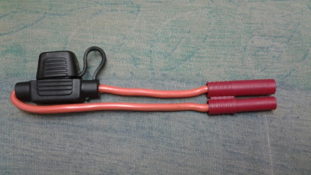
This safely handles the 35Amps maximum current without any chance of it accidentally blowing.
A fuse should only ever blow if there was a problem with the wiring, controller or motor which caused the current to exceed the rating of the fuse.
However, I did however manage to blow a 40Amp fuse when I inadvertently put the Smart Pie pack onto my bike with the tweaked Magic Pie and attempted to draw up to 50Amps from it. ::)

As Elmer has already mentioned, fuses are usually fitted on the positive side of the battery, but it will work just as well on the negative side of the battery, or even between cells or multiple batteries as Les mentioned:


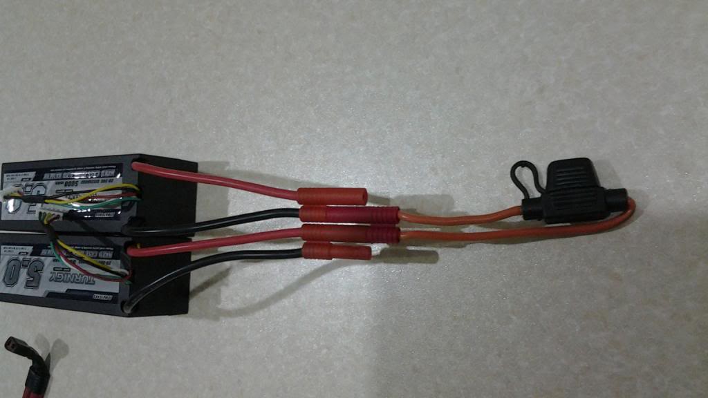
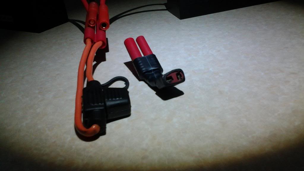
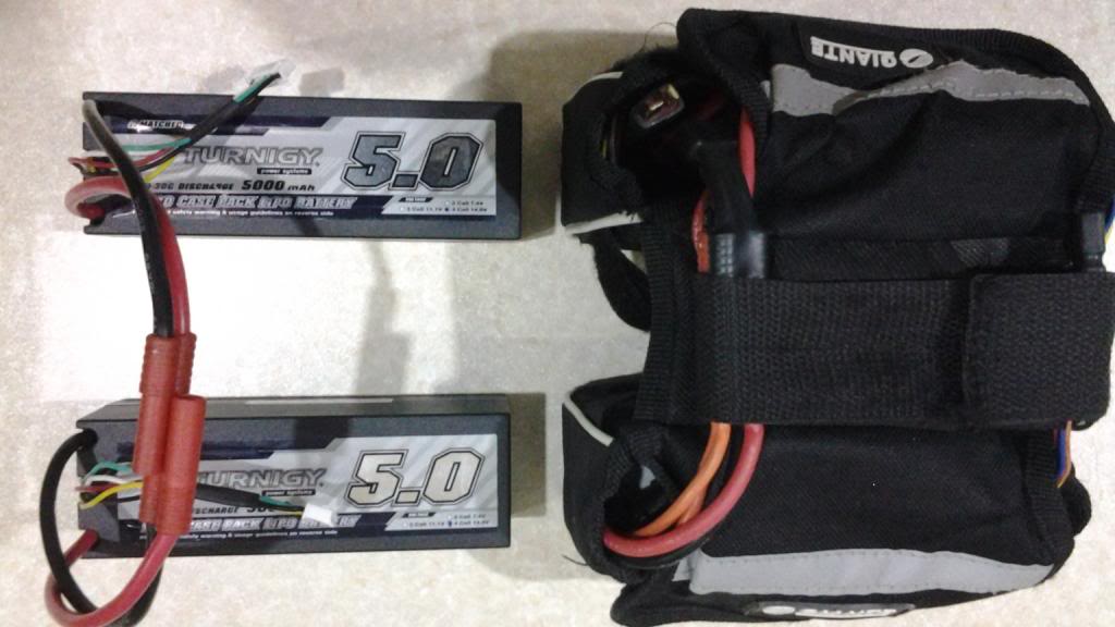
I actually have my fuse on the negative output lead of my pack, simply because I didn't want to change the connections on my battery balance lead adapter when I swapped the power output location from one side of the pack to the other:


Are you ok, nasty burns.

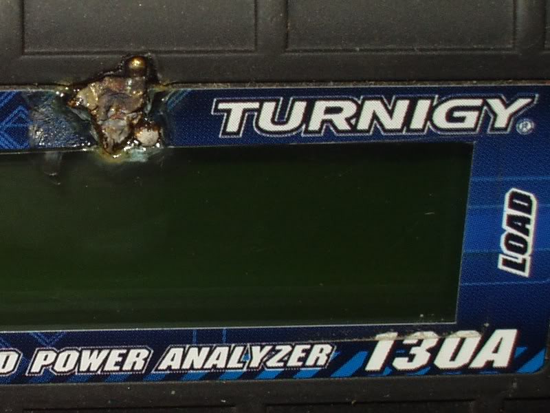
My fingers were fully healed within a week or two, but unfortunately my Turnigy Watt Meter is scarred for life from the resultant blob of molten copper:


Alan
 
« Last Edit: July 04, 2017, 10:26:04 PM by Bikemad »

Offline Greverif

  • Confirmed
  • New Member
  • *
  • Posts: 8
I have to buy à New connection like the one on the picture below. Its just like à pci-express connection but smaller. Does anyone know whats the exact name/brand/product number on this connection?
« Last Edit: August 16, 2013, 08:16:42 PM by Greverif »

Offline Greverif

  • Confirmed
  • New Member
  • *
  • Posts: 8
I did find the connection but it still didnt help. I also opened the wheel but all contacts seem fine. I guess the problem is in the throttle or the controller.

Offline Rodmiami

  • Confirmed
  • Bachelor of Magic
  • ****
  • Posts: 101
  Greverif , I posted before on your problem . Did you try resetting the Voltage to 24v or 36v ? Your battery only puts out 44.4 v well below the 48v you have the motor set at . Also do you have a 36v or 48v throttle . If it is 36v the lights will appear correct with a 44.4 v battery but the motor set at 48v will not turn . Rodmiami

Offline Greverif

  • Confirmed
  • New Member
  • *
  • Posts: 8
Thanks for your reply!

Yeah I have tried booth 24 and 36 v. Down below is a photo of the settings I use, but I have used 24, 36 and 48. Also, a very short video of what happens when I try to start the wheel. The throttle is a 48 v throttle. I just measured My battery pack and it was 50.1 v.

« Last Edit: August 22, 2013, 02:58:40 PM by Greverif »

Offline MAGICPIE3FOCUSPOWER

  • Confirmed
  • Master of Magic
  • *****
  • Posts: 372
Have you tested the hall sensors?

Offline Greverif

  • Confirmed
  • New Member
  • *
  • Posts: 8
Found the problem! It was the controller. Know I just need to know where to pass through the cable for the temperature sensor.