Right now I would appreciate knowing what your wire colors mean.
I assume I bought a 72 vdc 5000 watt motor.
A wiring diagram in USA English would be nice too.
What are the following wire colors?
Green?
Blue?
Yellow?
Also, how can I hook up the hall effect wires to read RPM's?
Thanks,
Dan
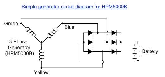
The three thick wires (which are shown on the diagram as Green, Yellow and Blue) go to the motor windings as per my diagram:

For simplicity I've shown the windings as a star configuration, but the motors may be wired in a delta configuration for all I know.
Either way it will have three heavy duty cables coming from the motor which will need to connect to a rectifier of some sort.
It doesn't matter which colours go to which connection so long as all three go to separate connections on the AC input side of the rectifier.
You should also have five smaller wires:
Small Red would normally have a 5V supply to feed the three hall sensors.
Small Black is the common ground (0V) for the three hall sensors.
Small Green, Yellow and Blue are the signal outputs for each of the three hall sensors.
I don't know how you can use the hall sensors to give an RPM output.
Hope this helps.
Alan