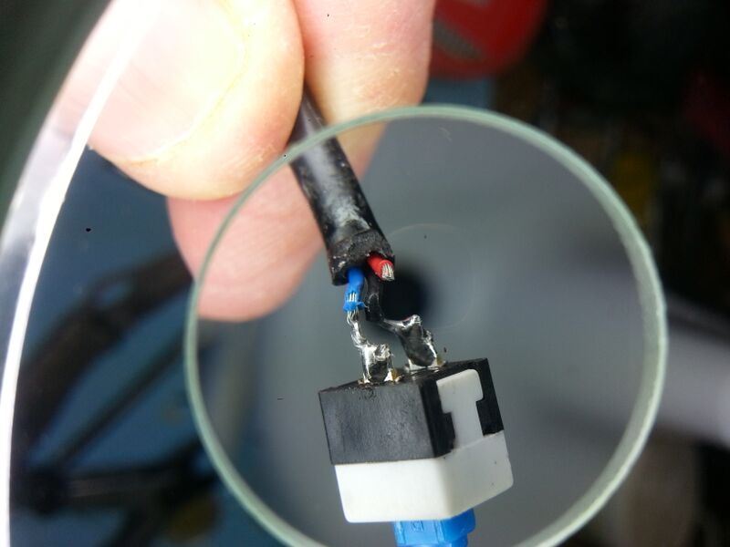
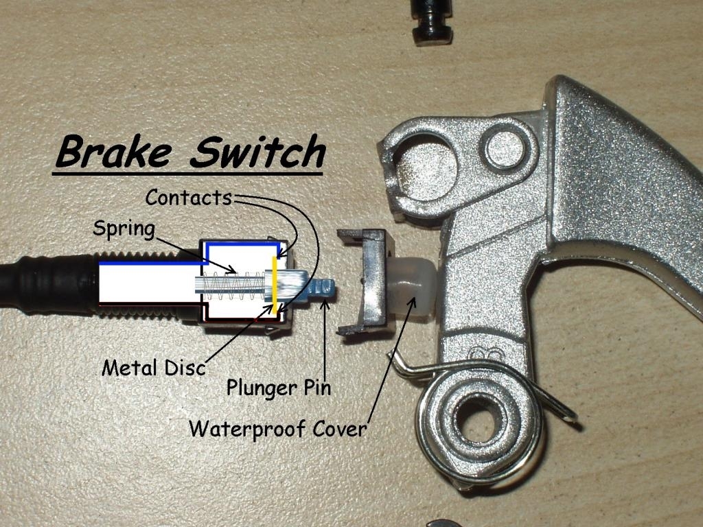
The GM wires for the brake switch are usually Red, Black and Blue, but only the Black and Blue are typically used with the standard GM mechanical brake switches as shown below:


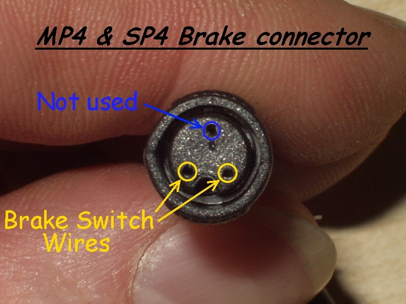
The above picture of the MP4 & SP4 brake connector also applies to the MP5, MPEdge and SP5 brake connectors.
The socket on the left is the Black ground wire connection and the socket on the right is the Blue brake signal wire connection.
The top socket Labelled as "Not used" is for the unused Red +5V supply wire.
The additional Red wire is a +5V supply for a Hall Sensor controlled brake sensing device, where a magnet is used to effectively switch the Blue signal wire to Ground
(Black wire) within the Hall Sensor when the brakes are applied.

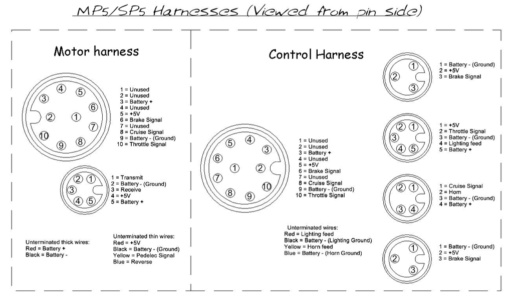
The three pin connectors in the above diagram show the connections of the wires on the control harness viewed from the pin side of the connectors, therefore the connections on the brake lever connectors viewed from the socket side are effectively a mirror image of those shown on the Control Harness layout.
Alan