Author Topic: Troubleshooting non functioning BAC-0501  (Read 11568 times)

Offline Cojust

  • Confirmed
  • New Member
  • *
  • Posts: 3
Troubleshooting non functioning BAC-0501
« on: June 18, 2017, 08:51:37 AM »
Bit of background: I have a BAC-0501 installed in a small electric vehicle built by a third party and I have zero documentation about it. I am trying to troubleshoot a unit which seems to have just died. If anyone has ANY information about how to get some sort of status info out of this thing I'll be happy to hear it  :(


Referring to the above image, the 5V terminal below C on the 12 pin connector does not have 5V present on it. Do I need to inject 5V, or is the controller supposed to output 5V on the terminal? I have measured this terminal with L and B+ connected, and with L and GND connected (which is how my vehicle seems to have been wired) but still no output.

The poster here seems to have the same issues, though he does not mention which 5V terminal he was measuring.

I also seem to recall someone mentioning on these forums that XS1 and XS2 can have a buzzer plugged in for status info, has anyone tried that?

I just saw https://goldenmotor.com/SMF/index.php?topic=448.0 and the corresponding diagram posted by Tom, am I right in saying that for the BAC-028 I need to connect B+ to GND?
« Last Edit: June 18, 2017, 08:55:44 AM by cojust »

Offline Bikemad

  • Global Moderator
  • Professor
  • PhD. Magic
  • ******
  • Posts: 5,553
Re: Troubleshooting non functioning BAC-0501
« Reply #1 on: June 18, 2017, 11:05:22 AM »
Hi andto the forum.

Unfortunately, there is very little information on the BAC-0501 controller, but I did find a photo showing most of the important connections:
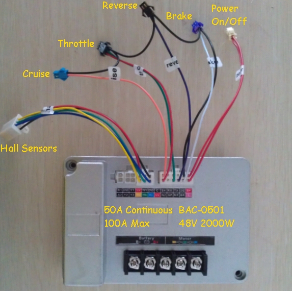
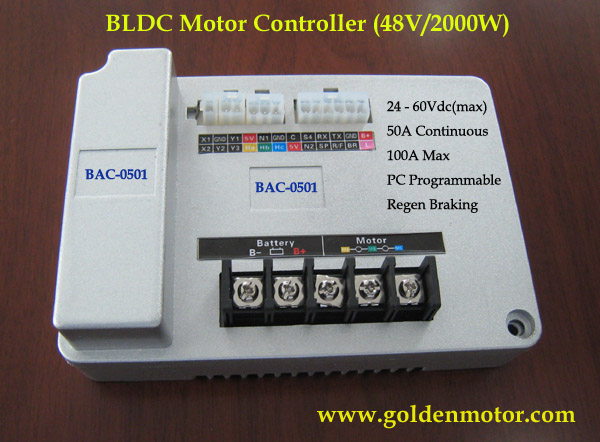


Referring to the above image, the 5V terminal below C on the 12 pin connector does not have 5V present on it. Do I need to inject 5V, or is the controller supposed to output 5V on the terminal?

Both of the +5V terminals should have ~5V output from the controller when the controller is powered on, if you don't have ~5V on either terminal, it is likely that the controller's integrated +5V regulator chip may have failed.

If this is the only part of the controller that has failed, applying an external +5V source should make the controller work again.
You should be able to test it using three AA batteries connected in series, but a simple DC:DC converter could be used as a permanent solution if the batteries allowed the controller to work again.


However, if more of the controller's electronics have failed, it is not going to be easy to find the cause of the problem without a detailed circuit diagram of the controller's board, and I have not come across one of those yet.

I have measured this terminal with L and B+ connected, and with L and GND connected (which is how my vehicle seems to have been wired) but still no output.

According to the picture I posted above, the L terminal should be connected to B+ to activate the controller (not to GND)

I also seem to recall someone mentioning on these forums that XS1 and XS2 can have a buzzer plugged in for status info, has anyone tried that?

I just saw https://goldenmotor.com/SMF/index.php?topic=448.0 and the corresponding diagram posted by Tom, am I right in saying that for the BAC-028 I need to connect B+ to GND?

I don't recall seeing one of these controllers with a horn connected like the BAC-028 controllers had, so I don't know if this controller uses the same beep codes for diagnostic purposes.

With the BAC-028 controllers it was necessary to connect the B+ to the "Gate" terminal (labeled "G" not "GND") to enable the controller.  ;)

Please let us know if the controller does work correctly again with an external +5V supply.

Alan
 
« Last Edit: July 04, 2017, 10:55:59 PM by Bikemad »

Offline Cojust

  • Confirmed
  • New Member
  • *
  • Posts: 3
Re: Troubleshooting non functioning BAC-0501
« Reply #2 on: June 18, 2017, 12:43:00 PM »
Thanks for responding!

Just to clarify, when you say
Quote
Both of the +5V terminals should have ~5V output from the controller when the controller is powered on
, do you mean when the battery is connected, or when L and B+ are connected?

I took apart a non working unit (but didn't take photos). Interestingly, it would appear that there are only 2 voltage regulators (labelled 8A 327 if anyone can identify what it is, looks to be a SOT22 or similar package), one connected to a microcontroller on the board and another to the 5V terminal near the hall effect pins. The 5V pin on the 12 pin connector SEEMS to only have the anode of a diode connected to it, but no regulator..

I know what you mean about connecting L and B+ to activate the controller as I have seen it elsewhere on the internet too, but here is a image of a working vehicle's connections...


Ignore the white, red and black cables from the bottom, those are floating and not connected to anything. You can see that L is tapped out on the connector, but B+ is not connected to anything.. I probably should trace out the cables and figure out where they go.

I will definitely update this thread, though the likely solution is to swap out the controller board since I have one on the way. Won't be anytime within these few days though..
« Last Edit: June 18, 2017, 12:47:17 PM by Cojust »

Offline Bikemad

  • Global Moderator
  • Professor
  • PhD. Magic
  • ******
  • Posts: 5,553
Re: Troubleshooting non functioning BAC-0501
« Reply #3 on: June 18, 2017, 06:23:44 PM »
Just to clarify, when you say
Quote from: Bikemad
Both of the +5V terminals should have ~5V output from the controller when the controller is powered on
, do you mean when the battery is connected, or when L and B+ are connected?

The controller is powered on when the battery is connected and the L and B+ is connected.

I don't know if it still produces a +5V output when the battery is connected and the controller is powered off (L and B+ disconnected).

Although the "B+" terminal on the 12 pin connector does not appear to be connected to anything, the "B+" supply may have been taken directly from the battery's + connector, and could be indirectly supplying the "L" connector with battery voltage via a remotely wired ignition/kill switch.
Tracing the wire coming from the "L" terminal may well confirm this.

Alan
 

Offline Cojust

  • Confirmed
  • New Member
  • *
  • Posts: 3
Re: Troubleshooting non functioning BAC-0501
« Reply #4 on: June 24, 2017, 12:29:49 PM »
So about that original controller: I think its dead given I read -50V across the +5V and GND (Yes, its negative). Swapped it out for another controller and everything works fine.

One thing to note for the BAC-0501: L is Active LOW. I wired up the new controller with the ignition switch connected across L and GND and it works. The second wire harness we have also has L and GND together in the same connector labelled "Power". Interestingly enough on the PCB you can see a set of pads which if bridged, would short L to GND. Simple way of disabling the lock?

These are images of a BAC-0501 (MX50A-3.0, though I opened up a MX50A-2.0 and nothing much seems to be different)


Both the 5V terminals on the board should read +5V upon activation. 5V on the 6 pin hall effect connector is supplied by U2, while 5V on the 12 pin connector is supplied by U4, which also supplies the main microcontroller.

This post suggests that the regulators are a SOT-89 78L05, supported by the markings on the chip (8A 327). You can see here and here (I made the assumption being a chinese product, they would use parts commonly available for them), the label is 8A 109, suggesting that 8A is the model and remaining 3 digits are a date code.

This would mean that the regulators have a maximum output current of ~100mA at best depending on which datasheet you look at, and lower with worst thermal dissipation, so this rail should only be used to power your throttle and other LOW current devices. My device was used to power a 7 segment display which I suspect killed the 5V rail.

This board also uses the STP140NF75, 3 for each phase side. Not sure if the thermal dissipation for these are enough, they are just pushed against a layer of kapton tape, thermal paste then the metal case.