Hi and

to the forum.
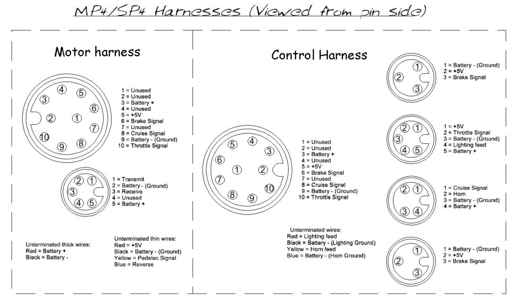
The MP4 should have a 10 pin connector between the motor and the main harness instead of the earlier 8 pin connector, but I have no idea what colour wires are used in either harness.

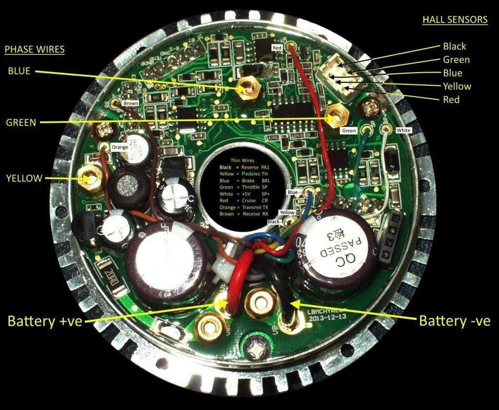
If you are able to straighten out the damaged pins to allow the plug and socket to be reconnected, you may be able to find out which colour wires are connected to each other by using a meter to measure continuity between the paired wires on both connectors.
The pin allocation should be as shown below:

Please note that the pin layouts shown on the above diagram are viewed from the pin/contact side of the connector, not the cable side.

I would expect the following 4 wires to be the same colour in the controller as they are in the motor harness 10 pin connector, but this does not necessarily mean that they will be the same:
Yellow = Throttle signal
Blue = Brake signal
White = +5V
Red = Cruise signal

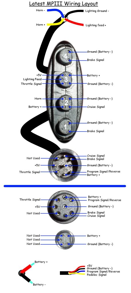
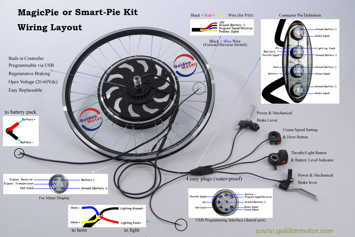
Here are two more diagrams, just in case your harness is actually the older 8 pin connector MPIII type:


The above MPIII diagrams are basically the same, except for the throttle connector pin configuration which is slightly different
(Lighting feed and Battery + wires are swapped on the most recent harnesses in the lower diagram).
Alan