Author Topic: MP4 Wire colors coming from the Pie's 8-Pin connector  (Read 4004 times)

Offline Marlz

  • Confirmed
  • New Member
  • *
  • Posts: 17
MP4 Wire colors coming from the Pie's 8-Pin connector
« on: August 06, 2016, 03:41:42 AM »
Hello,

A couple of the pins in the 8 pin connector were smashed when installing so we cut both ends of the connector to directly join the wires.  Unfortunately it seems that the wire colors are different.  I have read another thread talking about how to open the thumb throttle and figure out the wire colors on the throttle end, but what are the wire colors on the Pie end?

Any help would be greatly appreciated.

Offline Bikemad

  • Global Moderator
  • Professor
  • PhD. Magic
  • ******
  • Posts: 5,495
Re: MP4 Wire colors coming from the Pie's 8-Pin connector
« Reply #1 on: August 06, 2016, 05:18:04 PM »
Hi andto the forum.

The MP4 should have a 10 pin connector between the motor and the main harness instead of the earlier 8 pin connector, but I have no idea what colour wires are used in either harness.  :(

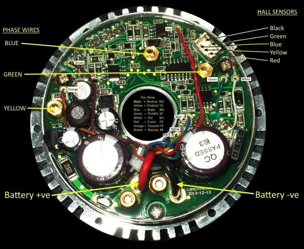
If you are able to straighten out the damaged pins to allow the plug and socket to be reconnected, you may be able to find out which colour wires are connected to each other by using a meter to measure continuity between the paired wires on both connectors.

The pin allocation should be as shown below:


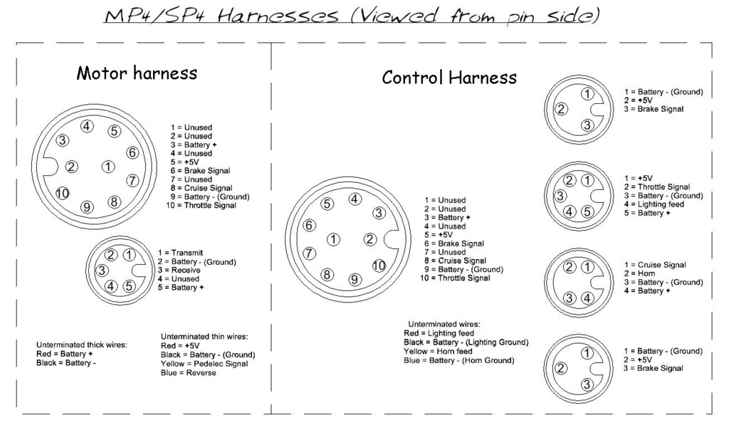
Please note that the pin layouts shown on the above diagram are viewed from the pin/contact side of the connector, not the cable side.  ;)

I would expect the following 4 wires to be the same colour in the controller as they are in the motor harness 10 pin connector, but this does not necessarily mean that they will be the same:
Yellow = Throttle signal
Blue = Brake signal
White = +5V
Red = Cruise signal


Here are two more diagrams, just in case your harness is actually the older 8 pin connector MPIII type:


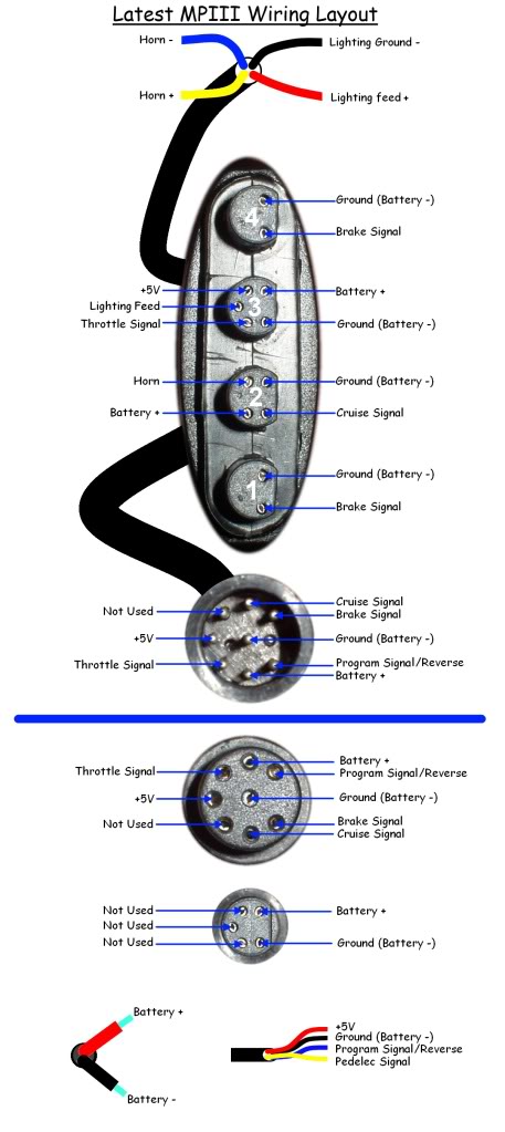
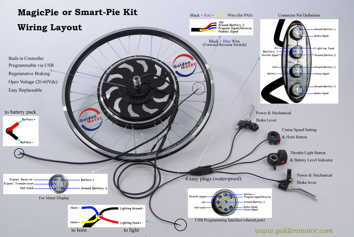
The above MPIII diagrams are basically the same, except for the throttle connector pin configuration which is slightly different (Lighting feed and Battery + wires are swapped on the most recent harnesses in the lower diagram).

Alan
 
« Last Edit: July 04, 2017, 11:14:23 PM by Bikemad »

Offline Marlz

  • Confirmed
  • New Member
  • *
  • Posts: 17
Re: MP4 Wire colors coming from the Pie's 8-Pin connector
« Reply #2 on: August 11, 2016, 02:09:41 PM »
First, thank you very much for your reply.  I have an electronic repair guy looking at the pie and he thinks he has the wires connected correctly but it is still not working.

So my question now is this:

Originally I thought that the throttle wires and the pie wires should be connected same color to same color and I connected them as such but it didn't work.  Do you think that connecting the wrong wires together could have damaged something?  If so, what might have been damaged?

Thanks again.

Offline Bikemad

  • Global Moderator
  • Professor
  • PhD. Magic
  • ******
  • Posts: 5,495
Re: MP4 Wire colors coming from the Pie's 8-Pin connector
« Reply #3 on: August 11, 2016, 03:31:40 PM »
If you have been able to determine the function of each of the coloured wires, you should be able to determine which wires would have been incorrectly connected.

If the battery + wire has been connected to the +5V wire, then it might have damaged the hall sensors in motor and/or the throttle unit, or possibly the +5V regulator on the controller's PCB. :o

I would first check whether the +5V output is still working from the controller (usually reads 4~5V), and if this is correct, I would then check the signal output of the throttle Hall sensor (this should vary between 0.8V~3.25V with the throttle movement) and the signal outputs of the three motor Hall sensors (which should alternate between 0 and ~4V when the motor is turned very slowly by hand).

If everything appears to be working correctly but the motor still doesn't run (even with both of the brake switch connectors unplugged), then it is probably due to a connection within the harness join that is still incorrect or shorted, or possibly a damaged controller.  :(

Alan