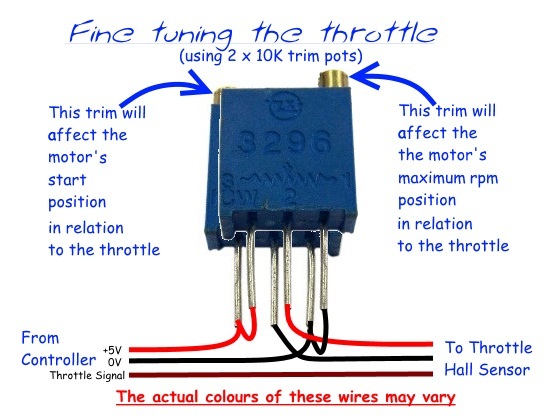
The throttle output signal is affected by three main factors
(assuming the +5V supply is always a constant 5V):
- The sensitivity of the hall sensor
- The strength of the magnets
- The proximity of the magnetic poles in relation to the sensor
Unfortunately, none of the above can be altered easily.
However, it should be possible to fine tune the operation of the throttle, but you would need to use a pair of 10k Ohms trim pot resistors to adjust the voltage at the +5V and 0V inputs of the hall sensor.
 Make sure the two resistors are pre-adjusted so the least resistance (ideally 0 Ohms) is between the two pins with the same colour wire (2 and 3 in the diagram) before you connect any power, as there's a good chance that it could actually supply the hall sensor with a reverse polarity feed if they were both accidentally adjusted the wrong way!
Reducing the +5V supply to the throttle should reduce the unresponsive 60-100% portion of the throttle movement and increasing the 0V supply should reduce the unused 0-20% portion of the throttle movement.
Adjusting the lower end setting will have a slight effect on the higher end setting
(and vice versa) so it may take a little bit of trial and error to get it adjusted just right.
Unfortunately, if the output from the 0V resistor is set too high, you may find that the power on safety feature of the controller will prevent the motor from running.
 Alan
Alan EDIT:
The vector controllers seem to have a different usable throttle range according to the battery voltage being used.
This would mean that the resistors would need to be readjusted if you changed the battery voltage setting in the controller.