Author Topic: Specs on wheel dimensions, Controlller diagram documents from GM, wires.  (Read 11313 times)

Offline Leslie

  • Confirmed
  • PhD. Magic
  • ******
  • Posts: 2,047
Documents from GM.


BLDC cables, wiring, plugs.PDF CLick here


I made thiis one for posting,  added colours etc.  Exported it to s lovley gif..

Its a big detailed pdf so get zoom in if you need..


Wheel Dimesions. PDF Click here


Not sure if you found these yet.

Plenty of stuff to look through.

http://goldenmotor.com/e-Bike-DIY
« Last Edit: October 05, 2008, 01:44:43 PM by 317537 »

Bring it on

Offline Leslie

  • Confirmed
  • PhD. Magic
  • ******
  • Posts: 2,047
Re: Specs on wheel dimensions, Controlller diagram documents from GM, wires.
« Reply #1 on: October 05, 2008, 06:08:34 PM »
This was what I was doing when I found the pdfs researching.

Updated


Full image drawn By Smee (317537)

Enjoy.
« Last Edit: October 06, 2008, 12:38:34 PM by 317537 »

Bring it on

Offline Leslie

  • Confirmed
  • PhD. Magic
  • ******
  • Posts: 2,047
Re: Specs on wheel dimensions, Controlller diagram documents from GM, wires.
« Reply #2 on: October 05, 2008, 06:29:54 PM »
Phase Calibration documentation..

Golden Motor Technology Co. LTD.
Regenerative Controller Self Calibration Procedure

Lift motor wheel up from the ground and attach it to a solid support stand. If the motor
is attached to the bicycle, attach the bicycle to an appropriate support stand capable of
solidly holding the bicycle with the powered wheel lifted at least 150mm (6”) from the
floor. Testing will be carried out at no load.

1 Make sure you have installed a heavy duty (30- 40 A) in-line power switch between
the battery pack and the controller on the positive side of both units. The battery pack
must have a nominal voltage of 24, 36 or 48 volts depending on your controller rating.
Controllers are voltage-specific, do not attempt to connect a controller to any other
voltage than specified, it will damage it, create a hazard and void your warranty.


2. Make sure power is off by detaching the battery pack connector. Make sure all
connections match the diagram above
. Please check all connectors on both sides
are properly seated. If you have a continuity tester (such as a multimeter) test every
connection by touching the opposite sides of each connection pin to verify they are
actually engaged. Verify the powerwheel is installed properly with the cable on the left
hand side of the bicycle.

3. Make a jumper by cutting a thin piece of gauge 18 to 22 wire, approximately 50mm
(2”) in length. Strip both ends to expose 10mm (0.40”) and bend it in a U shape.
4. On the controller box, find a 2 pin connector attached to purple and black wires.
This is the motor phase recognition connector. Insert the jumper into the 2 pin connector
so as to short it. This enables the controller to start automatic phase recognition
settings.

5. Make sure the system power switch is toggled off. Reconnect battery pack leads.
Toggle power switch on. If you have a multimeter, verify the correct voltage is being
supplied to the controller connector.

6. Gently twist throttle halfway to run motor for 2-3 seconds ONLY. See if the motor runs
smoothly, quietly, and in the correct direction (counter-clockwise observed from the
cable side on the motor)

7. lf yes, then remove jumper wire and toggle power switch off. The motor phase setting
is completed, the controller will remember the setting.

8. lf the motor still does not run smoothly, chokes, or spins in the wrong direction,
repeat step 5 (The maximum number of settings is 12. The controller will find the right
phase setting within 12 repetitions of step 5)


Another controller image from Golden Motor.
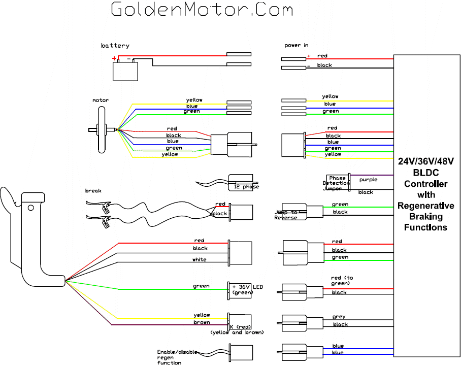


This one has the variable wire colours..
« Last Edit: October 05, 2008, 06:35:57 PM by 317537 »

Bring it on

Offline Leslie

  • Confirmed
  • PhD. Magic
  • ******
  • Posts: 2,047
Re: Specs on wheel dimensions, Controlller diagram documents from GM, wires.
« Reply #3 on: October 05, 2008, 06:48:23 PM »
More wheel dimensions..


Bring it on

Offline biohazardman

  • Confirmed
  • Bachelor of Magic
  • ****
  • Posts: 174
Re: Specs on wheel dimensions, Controlller diagram documents from GM, wires.
« Reply #4 on: October 05, 2008, 08:19:45 PM »
I was wonderin bout those pink ones thanks for clearing that up. Nice werq on the diagrams by the way and thanks for taking the time to do that.

Offline Leslie

  • Confirmed
  • PhD. Magic
  • ******
  • Posts: 2,047
Re: Specs on wheel dimensions, Controlller diagram documents from GM, wires.
« Reply #5 on: October 06, 2008, 11:06:16 AM »
I was wonderin bout those pink ones thanks for clearing that up. Nice werq on the diagrams by the way and thanks for taking the time to do that.

Pink ones???? hehehe, I don't have any pink ones on mine. I think GM are running out of colors to be honest.

You wouldn't dare short any jumpers without fully knowing what it does.

Just landed 2 more controllers frome EV-Power Australia, as always "peeeerfect". I have 3 working 36v controllers now. One of them will up for the mod...

Bring it on

Offline biohazardman

  • Confirmed
  • Bachelor of Magic
  • ****
  • Posts: 174
Re: Specs on wheel dimensions, Controlller diagram documents from GM, wires.
« Reply #6 on: October 13, 2008, 01:26:05 AM »
I was wonderin bout those pink ones thanks for clearing that up. Nice werq on the diagrams by the way and thanks for taking the time to do that.

Pink ones???? hehehe, I don't have any pink ones on mine. I think GM are running out of colors to be honest.

You wouldn't dare short any jumpers without fully knowing what it does.

Just landed 2 more controllers frome EV-Power Australia, as always "peeeerfect". I have 3 working 36v controllers now. One of them will up for the mod...
Well sorry you don't got the pretty pink ones. ;^)  Mine has shorted pink ones like on the first diagram although it is a 48v everything is the same color wise.  Thanks again.