Hi and

to the forum.
Unfortunately, there is very little information on the BAC-0501 controller, but I did find a photo showing most of the important connections:
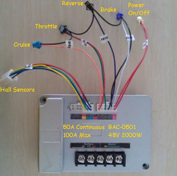
Referring to the above image, the 5V terminal below C on the 12 pin connector does not have 5V present on it. Do I need to inject 5V, or is the controller supposed to output 5V on the terminal?
Both of the +5V terminals should have ~5V output from the controller when the controller is powered on, if you don't have ~5V on either terminal, it is likely that the controller's integrated +5V regulator chip may have failed.
If this is the only part of the controller that has failed, applying an external +5V source should make the controller work again.
You should be able to test it using three AA batteries connected in series, but a
simple DC:DC converter could be used as a permanent solution if the batteries allowed the controller to work again.

However, if more of the controller's electronics have failed, it is not going to be easy to find the cause of the problem without a detailed circuit diagram of the controller's board, and I have not come across one of those yet.
I have measured this terminal with L and B+ connected, and with L and GND connected (which is how my vehicle seems to have been wired) but still no output.
According to the picture I posted above, the L terminal should be connected to B+ to activate the controller
(not to GND)I also seem to recall someone mentioning on these forums that XS1 and XS2 can have a buzzer plugged in for status info, has anyone tried that?
I just saw https://goldenmotor.com/SMF/index.php?topic=448.0 and the corresponding diagram posted by Tom, am I right in saying that for the BAC-028 I need to connect B+ to GND?
I don't recall seeing one of these controllers with a horn connected like the BAC-028 controllers had, so I don't know if this controller uses the same beep codes for diagnostic purposes.
With the BAC-028 controllers it was necessary to connect the B+ to the "Gate" terminal
(labeled "G" not "GND") to enable the controller.

Please let us know if the controller does work correctly again with an external +5V supply.
Alan


