Author Topic: Hall effect sensor tester  (Read 22053 times)

Offline huntley

  • New Member
  • *
  • Posts: 7
Hall effect sensor tester
« on: June 05, 2010, 09:30:16 PM »
Who42 shows a diagram to build a sensor tester that sounds pretty good. If I could figure out how to paste the figure of it here I would. So I apologize. The point here is that a 9volt battery is used, in series with a 470 ohm resistor to reduce the voltage to 5 volts. Who42 says "The 470ohm resistor and 9v battery combo = 5v was used because it limits the current some what and safer than using 4 AA batteries which would give 6v or 3 AA batteries at 4.5v and capable of to much current."  I put one of these testers together last night and I measured 2.08 volts on the far side of the 470 ohm resistor. I measured before the resistor on the resistor lead and have 9.25 v. coming in and I measured the after-resistor voltage on the outgoing lead at 2.08 volts. So I know it's not bad solder points. Why am I not getting a higher voltage reading. Can I use ohm's law someway to figure it out?

Offline Leslie

  • Confirmed
  • PhD. Magic
  • ******
  • Posts: 2,047
Re: Hall effect sensor tester
« Reply #1 on: June 05, 2010, 11:14:09 PM »
Hello and welcome.


You could replace that 470 ohm with a 4.3 volt 1 watt zener.  a   This has the exact voltage drop on the battery and will be forgiving under a changing load when the leds switch and allow enough current to your leds

Then Id place a filter cap over the hall input and ground to filter out any noise you could be getting off the zener.

I don't like the circuit really as the led change the load over that resitor when they change from two to one and back again.  It creates a pulse noise in the voltage over the resitsor.  Those little hall sensors draw only a little amount of current.

Hang for a little and I will make one up.

Bring it on

Offline Bikemad

  • Global Moderator
  • Professor
  • PhD. Magic
  • ******
  • Posts: 5,508
Re: Hall effect sensor tester
« Reply #2 on: June 06, 2010, 01:33:54 AM »
I put one of these testers together last night and I measured 2.08 volts on the far side of the 470 ohm resistor. I measured before the resistor on the resistor lead and have 9.25 v. coming in and I measured the after-resistor voltage on the outgoing lead at 2.08 volts. So I know it's not bad solder points. Why am I not getting a higher voltage reading. Can I use ohm's law someway to figure it out?

The reading is so low because the red led is loading the 470 ohm resistor too much, if you remove the red LED from the circuit, you should find it will work correctly:


You could try putting another 1K resistor in series with the red LED if you particularly want to use it as shown below in the modified diagram.

Alan
 
« Last Edit: June 06, 2010, 03:01:12 AM by Bikemad »

Offline Leslie

  • Confirmed
  • PhD. Magic
  • ******
  • Posts: 2,047
Re: Hall effect sensor tester
« Reply #3 on: June 06, 2010, 08:31:33 AM »
doh I didnt even see red led there there.

Silly me,

Bring it on

Offline huntley

  • New Member
  • *
  • Posts: 7
Re: Hall effect sensor tester
« Reply #4 on: June 06, 2010, 07:35:14 PM »
Thanks, Bikemad. I put the 1K resistor in front of the red led and that upped the reading to 6.62 volts. Is that going to be too much for the hall sensors? Should I try a 470 ohm resistor instead? Thanks

Offline Leslie

  • Confirmed
  • PhD. Magic
  • ******
  • Posts: 2,047
Re: Hall effect sensor tester
« Reply #5 on: June 06, 2010, 08:27:33 PM »
Place a amp meter between the ground and resistor and test how much currnet goes through the resistor and adjust resistor to meet led spec.

If your led draws like my test led. 50ma

You want at least a 6v drop at 50ma so you need .5 resistor.


You want 9v/.050A=180 ohm
 
2v led at .050A, a 40 ohm on.

180-40=140

as close to 140 ohm. But it must go on the 9v terminal not the 470 ohm.


« Last Edit: June 06, 2010, 08:41:03 PM by 317537 »

Bring it on

Offline Leslie

  • Confirmed
  • PhD. Magic
  • ******
  • Posts: 2,047
Re: Hall effect sensor tester
« Reply #6 on: June 06, 2010, 08:53:38 PM »
Ok I am building a E-bike lab box from parts that any enthusiast should be able to get their hand on.


At the heart of this box I have 2X15va power transformers that will be limited to 1 amp each.  They have good isolation at 30v.


So here is the plan.

It will be a cell charger up to 29.4v with a home made BMS.  It will have a hall tester and throttle tester.  I and I am going to install a inductance meter as well to test the windings.


Bring it on

Offline Leslie

  • Confirmed
  • PhD. Magic
  • ******
  • Posts: 2,047
Re: Hall effect sensor tester
« Reply #7 on: June 06, 2010, 09:07:09 PM »
Here is a led on a 9v battery.  This is a nimh rechargable and needs a bit of Juice.

The resistor is two 70 ohm 1/4 watt in series. .5 watt 140 ohms. total.


The led would prolly go dark when the battery was flat too.

I want my lab to have the right stuff in it,  Some help with some new designs would be great.

« Last Edit: June 06, 2010, 09:10:14 PM by 317537 »

Bring it on

Offline Dummy Dave

  • Confirmed
  • New Member
  • *
  • Posts: 24
Re: Hall effect sensor tester
« Reply #8 on: June 06, 2010, 10:17:17 PM »

The resistor is two 70 ohm 1/4 watt in series. .5 watt 140 ohms. total.


Sorry amigo.  Each resistor sees the total current, so it's 1/4 watt, 140 ohms total.

-Dave

Offline Bikemad

  • Global Moderator
  • Professor
  • PhD. Magic
  • ******
  • Posts: 5,508
Re: Hall effect sensor tester
« Reply #9 on: June 07, 2010, 12:35:28 AM »

The resistor is two 70 ohm 1/4 watt in series. .5 watt 140 ohms. total.


Sorry amigo.  Each resistor sees the total current, so it's 1/4 watt, 140 ohms total.


Dave, I think you'll find that Leslie is 100% correct in this instance.

If a single resistor can handle 0.25 Watts, two resistors in series will handle a total of 0.5 Watts (0.25 Watts each).
Although the Current is the same in both resistors, the Voltage across each resistor is not, it's only half the total voltage.

Try and think of it in terms of light bulbs, where the filaments are basically simple wire resistors enclosed in a gas filled glass container, and it might be easier to understand:

  • A 12V source powering a single 12V 10 Watt bulb will have a current draw of ~0.83 Amp. (Watts = Volts x Amps)

  • A 12V source powering two 6V 5 Watt bulbs in series will also have a current draw of ~0.83 Amp.

The Current and the total Wattage remains the same, but the actual Voltage across each bulb is reduced by half to just 6V.

Although I'm not very good at explaining how and why, I do know that Leslie is right, and I'm hoping that you will be able to see this too.

If you're still not convinced, try some simple calculations using the formulas (formulae) below and check your results.

Alan
 

Offline Leslie

  • Confirmed
  • PhD. Magic
  • ******
  • Posts: 2,047
Re: Hall effect sensor tester
« Reply #10 on: June 07, 2010, 04:24:27 AM »
I was calculating the heat watts needed to burn 6v 50ma, I figured I used 2 series 70 ohm 1/4 watt resistors each would divide the voltage drop into 2, 3v each resistor. So 3vX0.05A = .15 watts. For both resistors that would be .3 watts so I said a half watt resistor as this is standard and its good to give yourself a 3/2 overhead ratio with the .5 watt series divider,

Anyway,

We need to rectify the AC power transformers.  Note I have not removed the original 220v AC connection so all I am playing with as it seems  15vdc at one amp. For each of these.

This tranformer is a multi-cenret-tap 15va transformer.  I am going to use the neutral phase push for a positve DC rail and the active phase push for a positive DC rail and the center tap for ground.


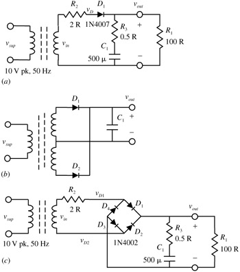
The first two are half wave rectifiers, the first is with no center tap, one and the other, like mine with a centre tap.  The third is a full wave recifier. It uses a trick where you can gain rail output by rectifying both push and pull phases of both neutral and active of the AC output of the transformer..

half wave rectifier

I used some IN5404 recifier diodes to convert the AC into DC wave form.  Doing like this onto the transformer means I wont need to install diodes to any device I choose to us on it.

There are some different ways to mac the AC into DC.  This half wave rectifier is very basic and keeps the volts per one amp VCA close to the rail voltage.


The Black wire will be ground, and the the end points of the diodes will be the output.

Edit sorry for the wrong process.
« Last Edit: June 07, 2010, 05:01:38 AM by 317537 »

Bring it on

Offline Leslie

  • Confirmed
  • PhD. Magic
  • ******
  • Posts: 2,047
Re: Hall effect sensor tester
« Reply #11 on: June 07, 2010, 05:12:13 AM »


If you're still not convinced, try some simple calculations using the formulas (formulae) below and check your results.

Alan


How I came up with the formula is based on Ohms law like you say.

V/I=R

So I saw his voltage over that diode and it was the led.  2v Is close enough,


If it was a 50 ma led we need 50ma to pass any resistor.

Lets find the resistance of 9v @.05A .  9v/.05a=180 ohms.

We can not exceed 180 ohms in our circuit.

Lets find the resistance of the Led switched on.

2v@.05a 2v/.05a = 40 ohms.

Now we need to calculate the left over resistance from the 180 ohm.

180-40 = 140ohm

When in series with the led .05 amps is allowed to pass at 9v.

Now we need to calculate the wattage resitor.

P=VdXI

P= watts

Vd= voltage drop.

I= current

Voltage 1 (9v) minus voltage 2 (2v led)

V1-V2 9-2=8v

Vd= voltage drop= 8v*.05a = .04 watts

Use a 140 ohm, 1 watt but I found .5 fine.


« Last Edit: June 07, 2010, 05:26:53 AM by 317537 »

Bring it on

Offline Leslie

  • Confirmed
  • PhD. Magic
  • ******
  • Posts: 2,047
Re: Hall effect sensor tester
« Reply #12 on: June 07, 2010, 06:58:02 AM »
We build a new hall sensor tester out of this supply voltage and much more.  We can soon use some IC's to regulate the current and voltage properly.

These two transformers are wired in series with a half wave rectifier on each series output with no filter (capacitor) yet.  They will be able to run paralell up to 15v at 2 amps or series 30v 1 amp charging station for both SLA Lifepo, Lipo, Lets put a single cell charge abilty in there too and a soild 1 to 2 amp constant current supply.

We have a good 40 VDC 50% swfm 50hz rail voltage.

Those 2 transformers both tested 20.02 and 20.01v, so no presence of isolation problems here.
« Last Edit: June 07, 2010, 07:13:56 AM by 317537 »

Bring it on

Offline Leslie

  • Confirmed
  • PhD. Magic
  • ******
  • Posts: 2,047
Re: Hall effect sensor tester
« Reply #13 on: June 07, 2010, 12:02:03 PM »
My transformer is now charging an SLA battery.  I used a 2,200uf cap to filter out the rectified DC current clean and use a LM317t in constant current mode.


In this pic I use a 1.5 ohm resistor and this regulates to .83a.


Lm317t current formula

1.25v/I

1.25v/1a= 1.25 ohms

I then bump up the resistnace to 1.22 ohms.


Perrrrfect.


This will hold one amp over any voltage under 15v or very close.  I need it to be spot on.


I just need to see at 15v and still draw 1 amp.

Then configure a switch so when the battery reaches 15v it switches to another regulator 13.76 @ 1 amp.
 
« Last Edit: June 07, 2010, 12:19:39 PM by 317537 »

Bring it on

Offline Leslie

  • Confirmed
  • PhD. Magic
  • ******
  • Posts: 2,047
Re: Hall effect sensor tester
« Reply #14 on: June 07, 2010, 12:24:13 PM »
SLA is at 13.33v at a rock solid 1.00 amp supply.

Bring it on