Hello All
Recently I have been asked how to install the External Magic Pie II, and looking at the install guides this is not really covered. One is for the HBS motors and one for the Internal Magic Pie. So today I built yet another bike and decided to take a lot of pictures to see what I could come up with.
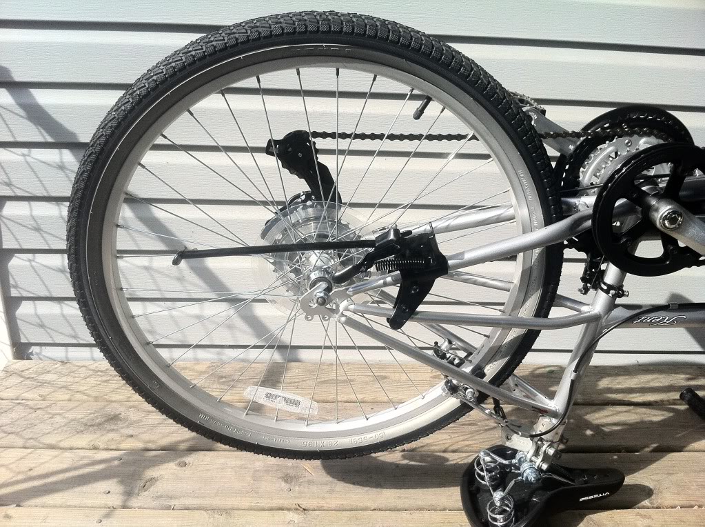
First you start with your bike upside down and take off the wheel. This install is for a rear wheel so if you are doing a front you can skip by some things.
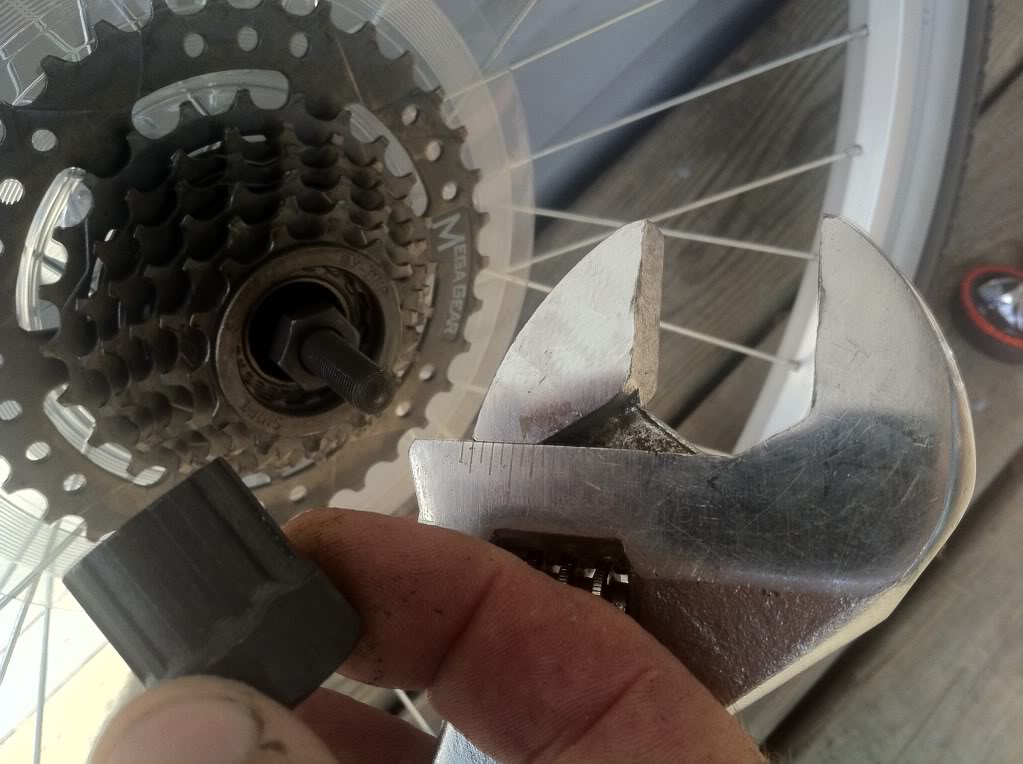
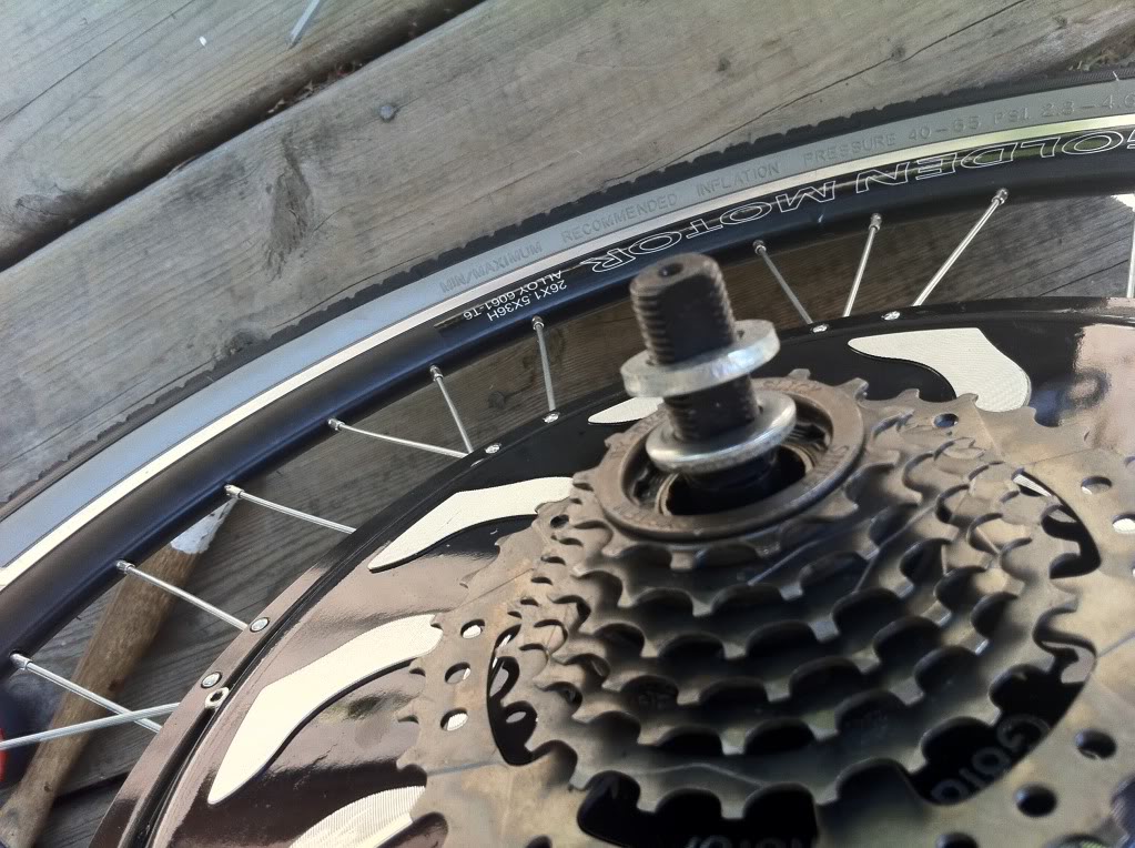
Then with the wheel removed, you have to unscrew the freewheel in an anticlockwise direction using a freewheel removal tool and a suitable wrench. This is if you want to use your existing freewheel. A six speed is ideal; a seven speed will involve a little bit more work.
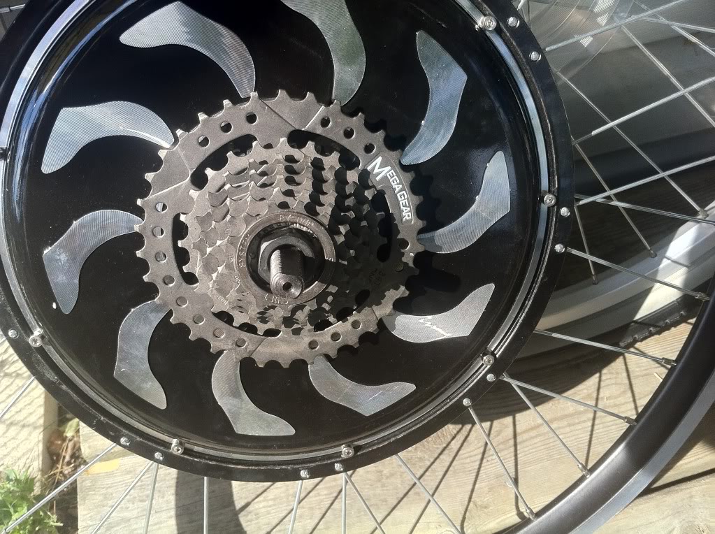
Next you have to carefully spin the freewheel onto the new wheel. Tighten it as much as possible by hand and then check that it still free-wheels easily in the reverse direction.
If you are using our 6 speed freewheel this should work fine. If you are using a seven speed or any other it may bind and not freewheel. In this case you have to remove the freewheel and add the spacer ring you should have received with your kit. You may want to look at the first part of this video to see what I mean about the freewheel possibly binding.
http://www.youtube.com/watch?v=o31OwsCzxyI&list=UUv3KWOO85wyf-opGp2gn-yA&index=1&feature=plcp
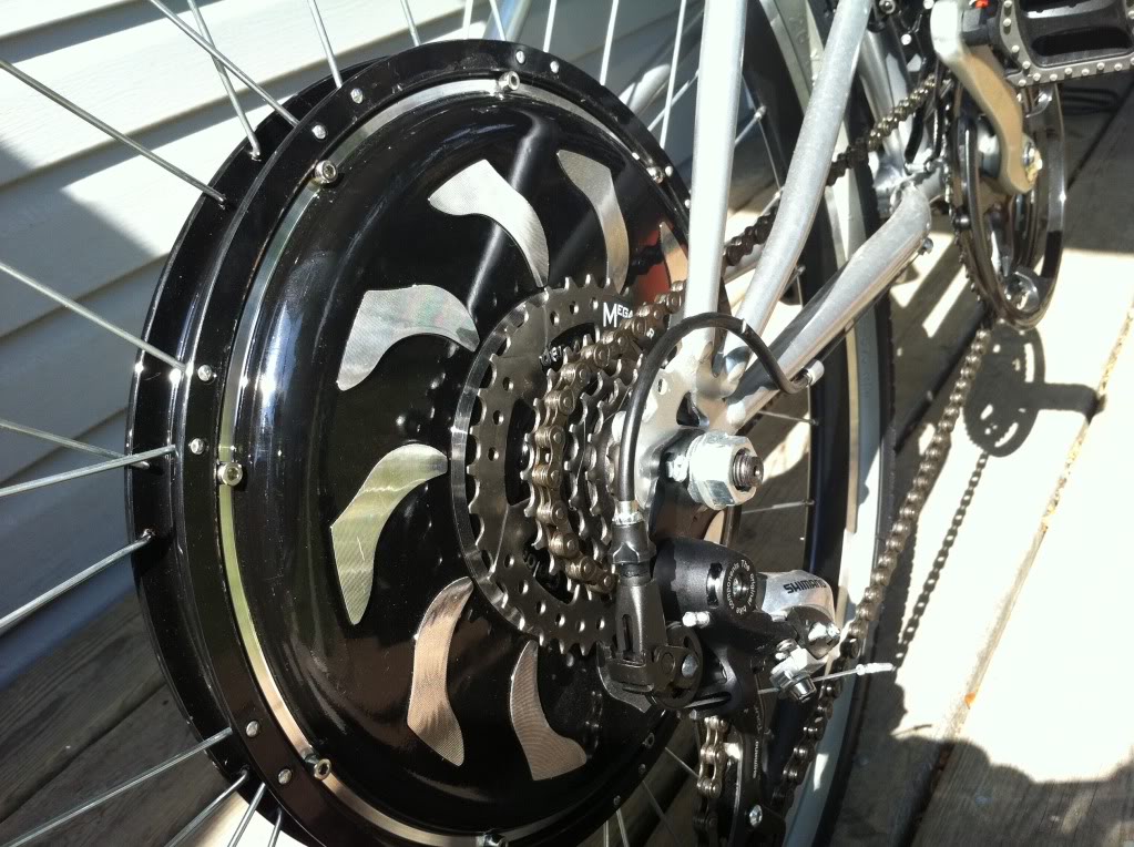
Next if you are going to use a disk brake install the brake disk to the other side. In most cases I find using a spacer ring behind the disk is a good idea as it will help keep the activator from rubbing on the motor. No picture for this at this time as this build did not use a disk brake. Maybe I’ll add one in later.
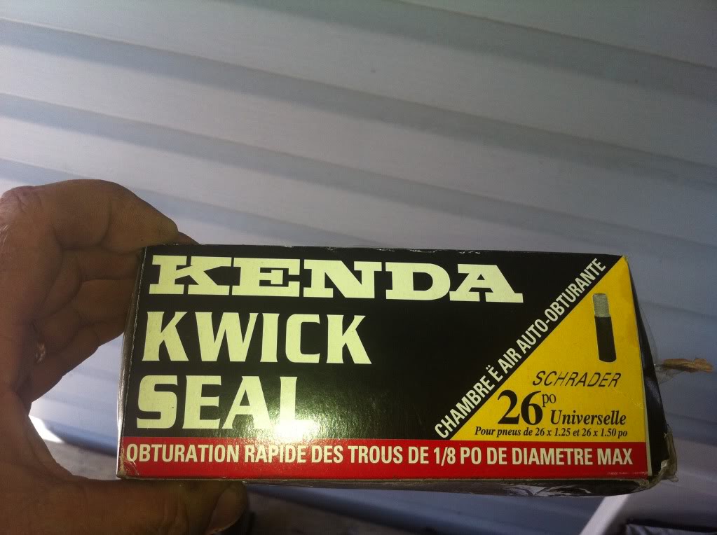
Next remove the tube and tire from your existing wheel and fit them onto the new wheel. I usually replace any cheap tube at this point with a nice thick self sealing tube like this one.
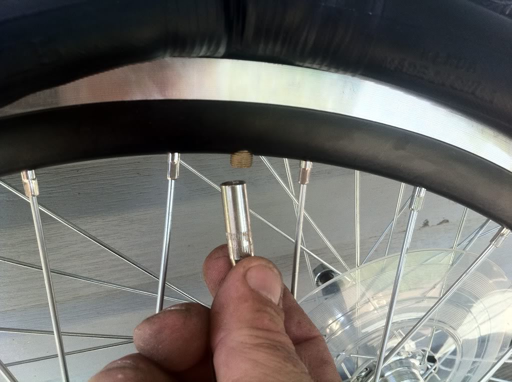
I find fitting a valve extension is very handy here to keep the valve from going inside when you air it up. They can be picked up at any tire shop.
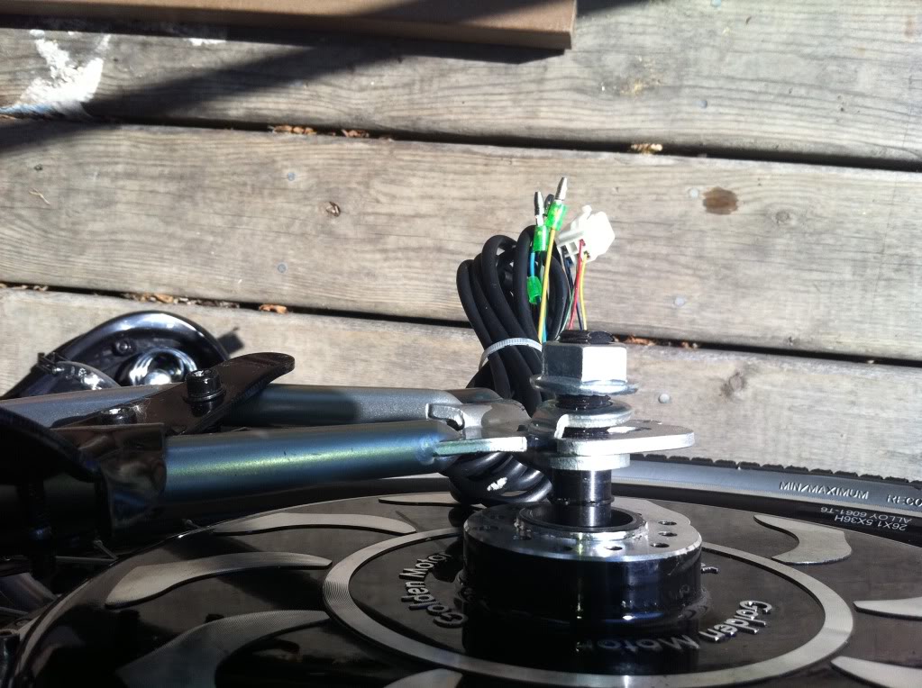
Next take all the washers and nuts off the wheel except one flat one on each side. If you are using a seven speed freewheel you will need to have at least 2 or 3 washers on that side to prevent the freewheel from binding against the frame. You also have to ensure the washers do not make contact with the freewheel in any way or it will bind.
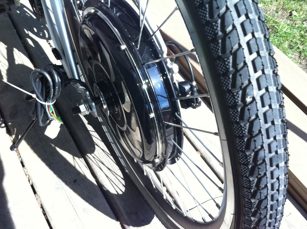
Next place the wheel into the frame. Be sure the wires do not get damaged and are pointing in the direction you desire. The washers are positioned as shown. First one flat one (2 or 3 if using a seven speed freewheel), then the bike dropout, then the lock washer with the tab pointed into the opening of the dropout followed by the nut.
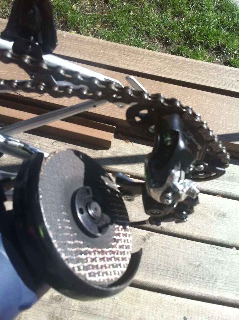
If it fits ok great, but sometimes the dropout slot is slightly too narrow and you may need to file the slot wider to accommodate the 10mm flats on the axle. This can be done with a file in 15 to 20 minutes or an angle grinder in 15 to 20 seconds. Be careful not to overdo it.
Now make sure the wheel is correctly aligned and the axle nuts are done up very tight before turning the bike over. Here are a couple of shots with the wheel fitted.
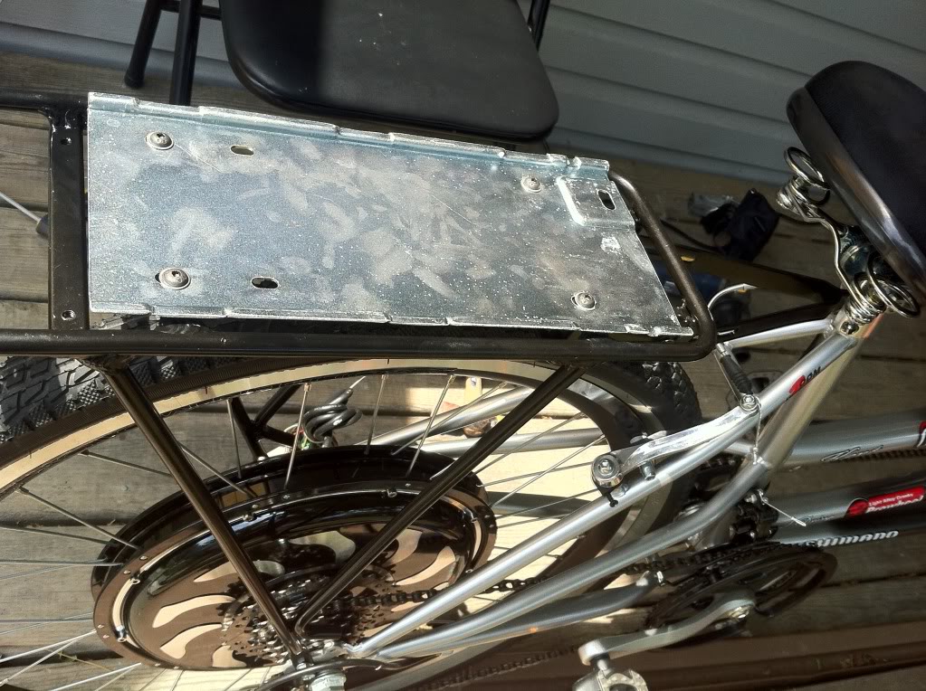
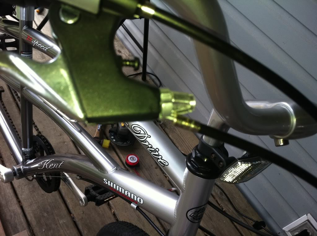
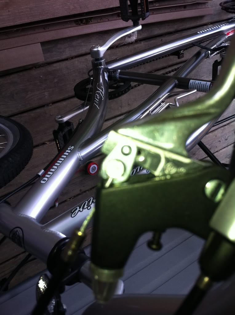
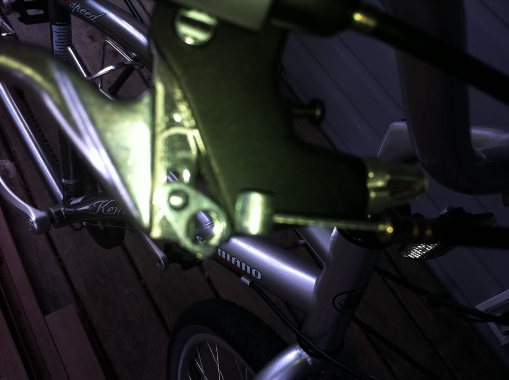
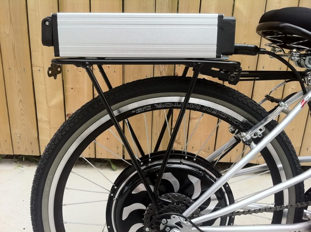
Next add the rack for the battery; this one is the rak-001 (standard rack). I prefer this rack as it is very strong and doesn't move.
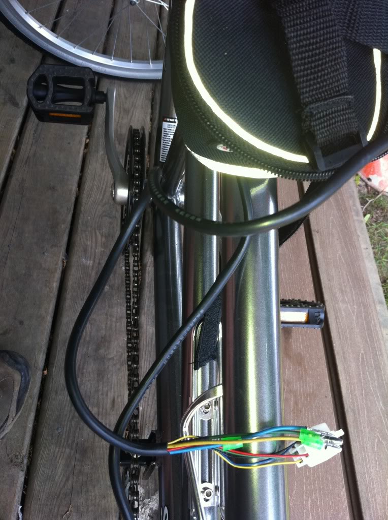
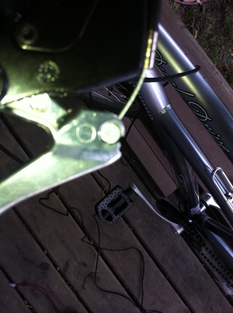
Next pick a location for all the wires to meet the controller. I like hanging a pouch under the seat. Others prefer the controller box under the rack. Remove the plastic tie from the motor wires and then run them to the Pouch (in my case). In through the bottom and out the zipper opening.
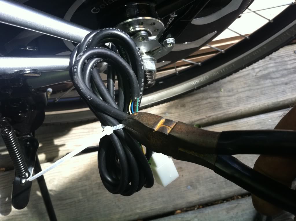
Now connect them to the controller wires as shown.
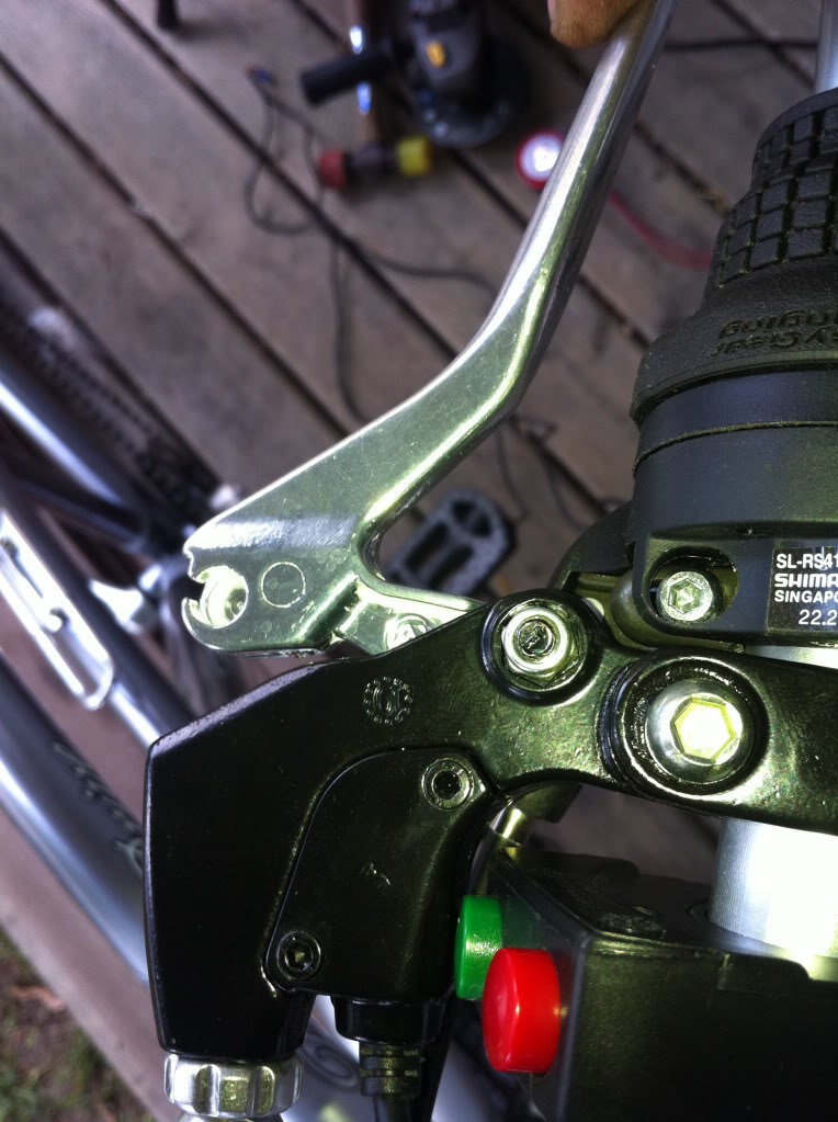
The motor is now installed; let's move on to the controls. First the brake levers need to be removed, the brake cables can stay you are just replacing the handles.
Once the cables are disconnected you can remove everything from the handlebars and install the throttle, control buttons and power brake levers. Although the old rubber handle grips are usually a snug fit, they can sometimes be removed quite easily by using the slackened brake lever assembly (or the twist gear selector) to push them off by applying force to their inner end, instead of trying to pull the grips.
If the rubber grips have holes in the outer end, put your finger over one hole and use a bicycle pump or airline on the other end to simply blow them off. If they still refuse to budge (and you are not intending to reuse them) you may have to resort to cutting them off.
Then reconnect the brake cables to the new levers. Tighten everything up and add the new handle grips. Depending on how much room you have they may need to be trimmed to fit.
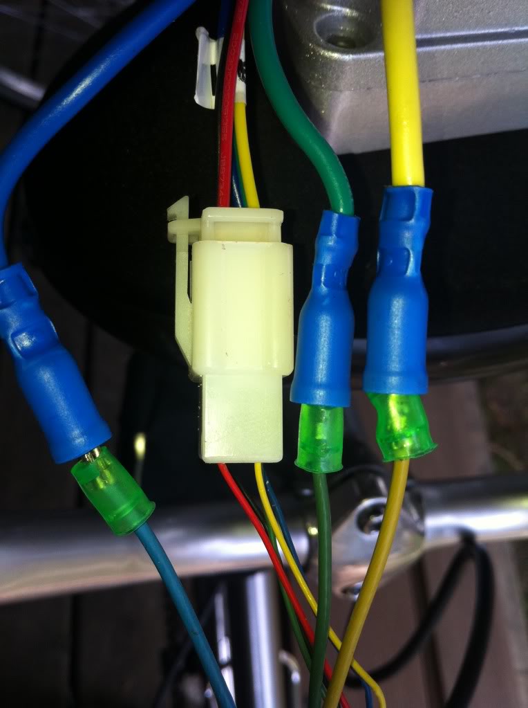
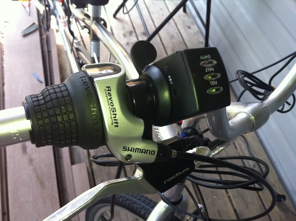
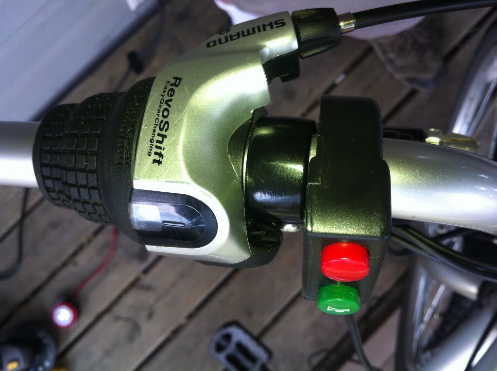
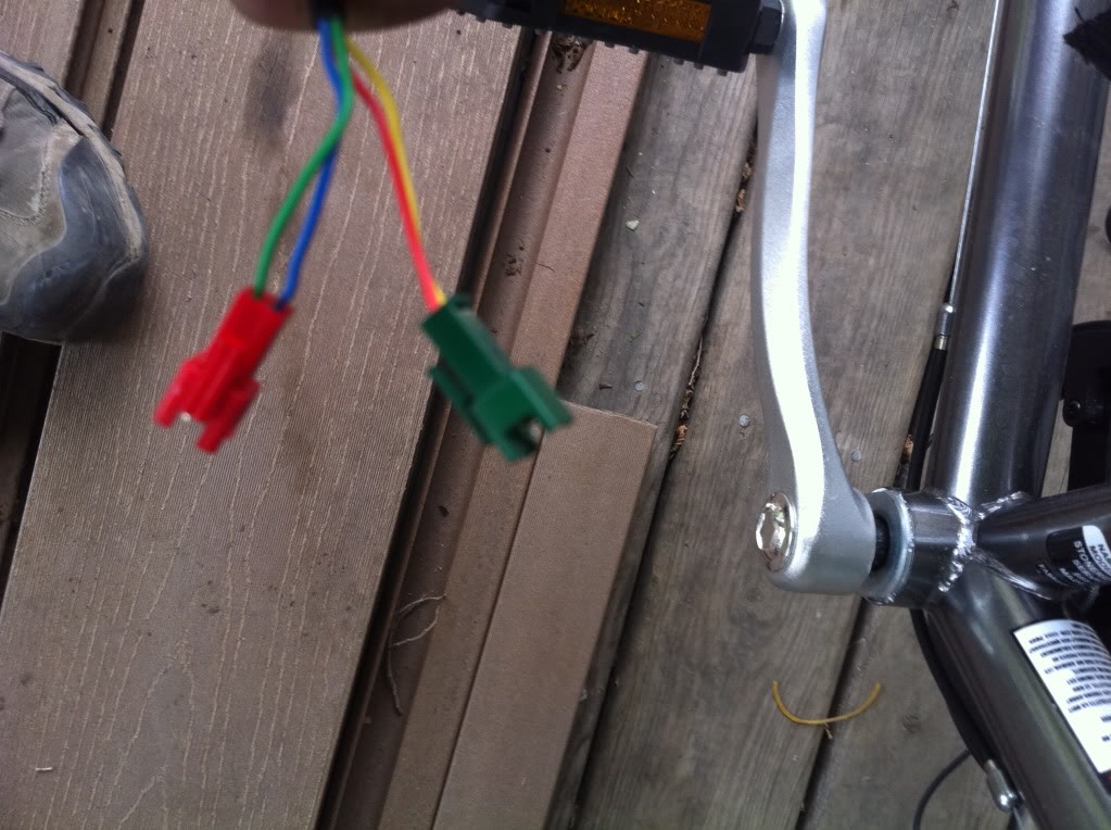
Now for the wiring of the controls. First the wires from the throttle. The black 3 pin plug is the throttle plug. The two pin yellow plug is for the battery indicator LED’s in the throttle and the two loose wires are from the red switch on the throttle. This can be used for lights, reverse etc.
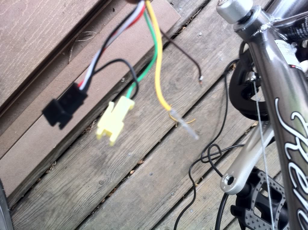
In this example I'm using it for the reverse function. Look in the bag of extra plugs you received for the 2 pin black one and add it to the loose yellow and black wire from the throttle.
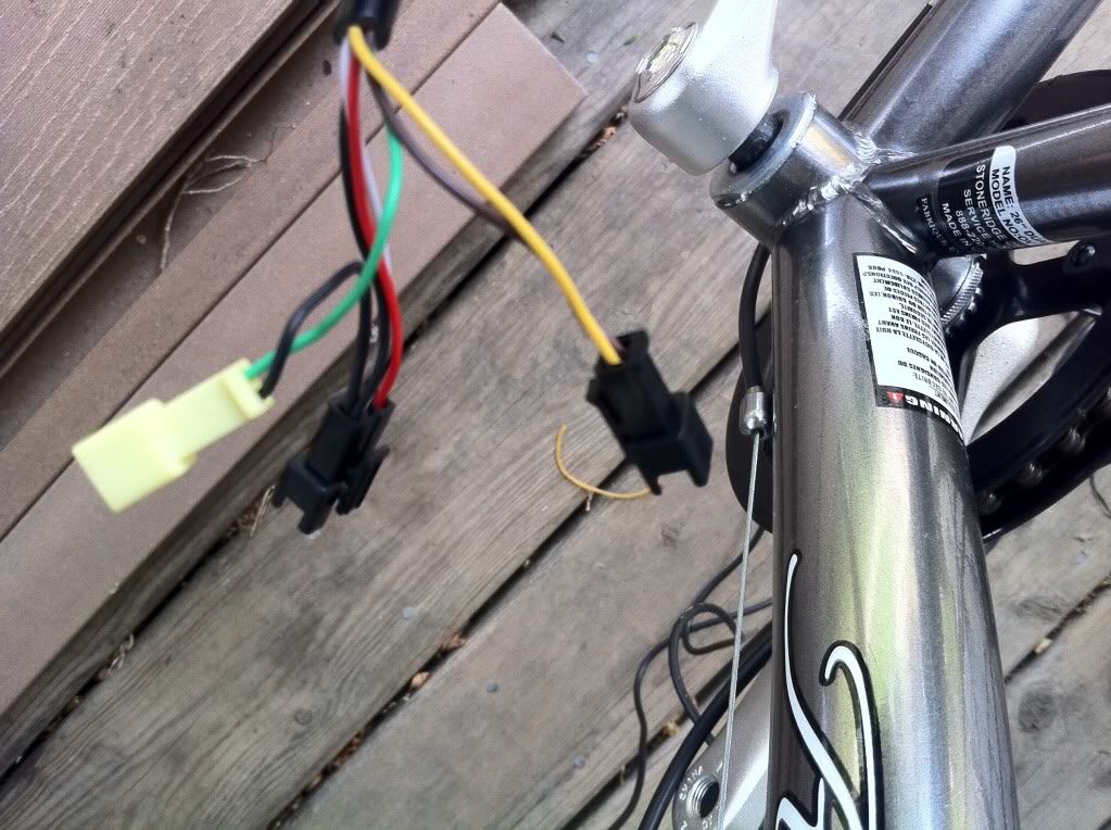
Now plug them into the matching colored plugs from the controller.
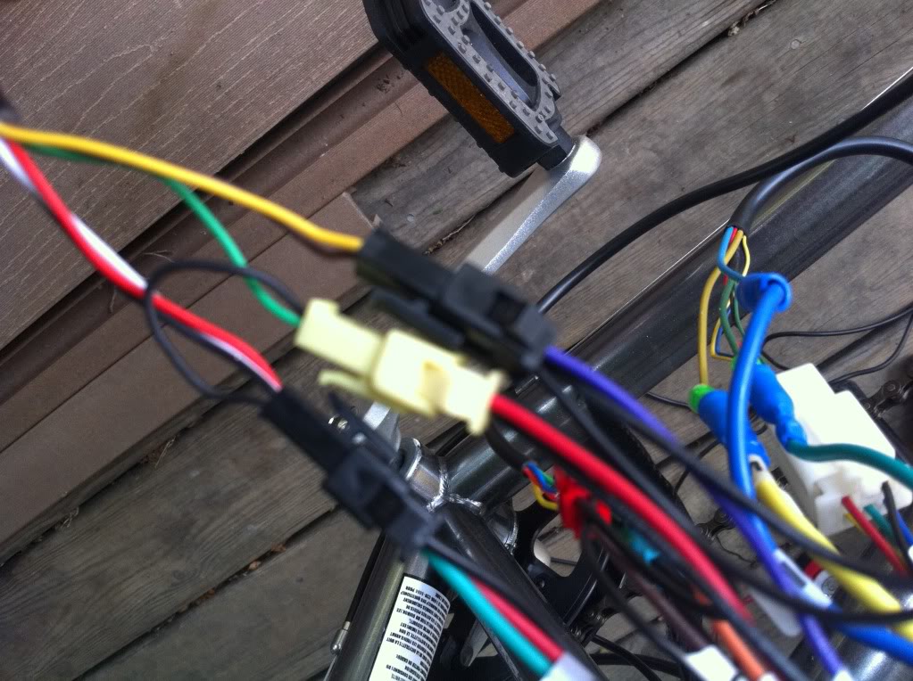
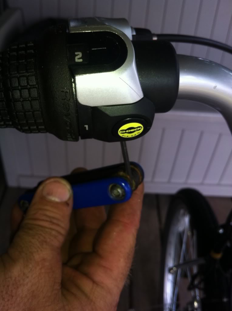
Next the 4 wires that come from the 2 button switch. The yellow and red are usually in a green plug. That is for the red button on the switch usually used for cruise control. The blue and green is for the green button which we will use for the horn.
Please note if you have a 3 button switch you should have a look at this
photo of the 3 button switch wiring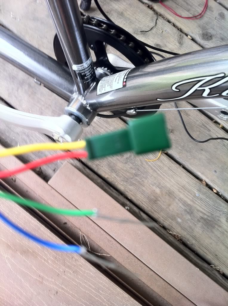
Add a red plug to the green and blue wires.
Then plug the green and red to the matching colored plugs on the controller. Please note that the green plug on the controller is a different shade of green but it should be tagged cruise.
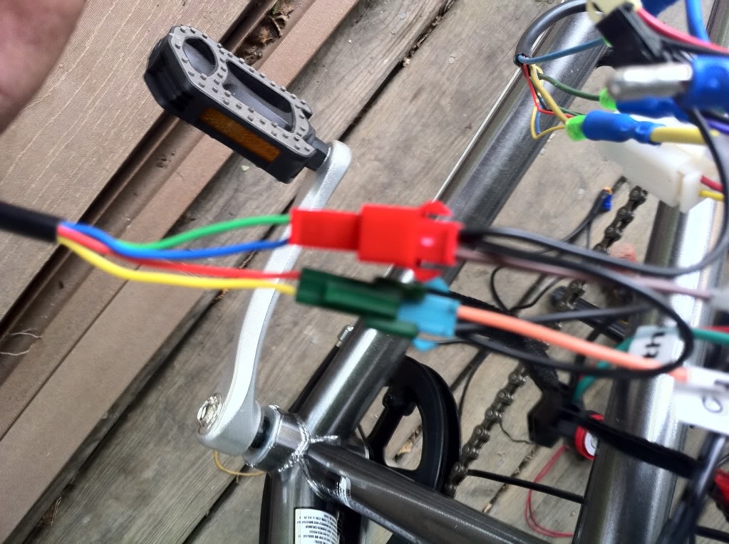
Now for the brake levers. Plug the blue plug from the brake levers to the blue plug (sometimes purple) on the controller.
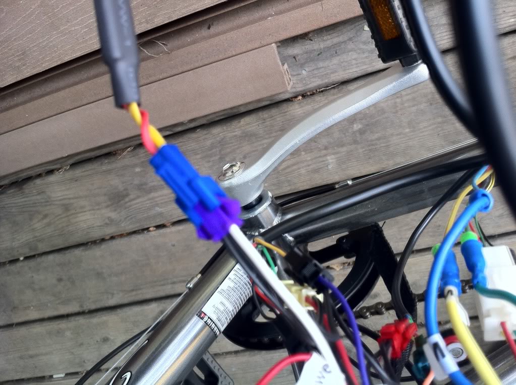
Next hook up the black and red wires from the battery to the black and red wires from the controller.
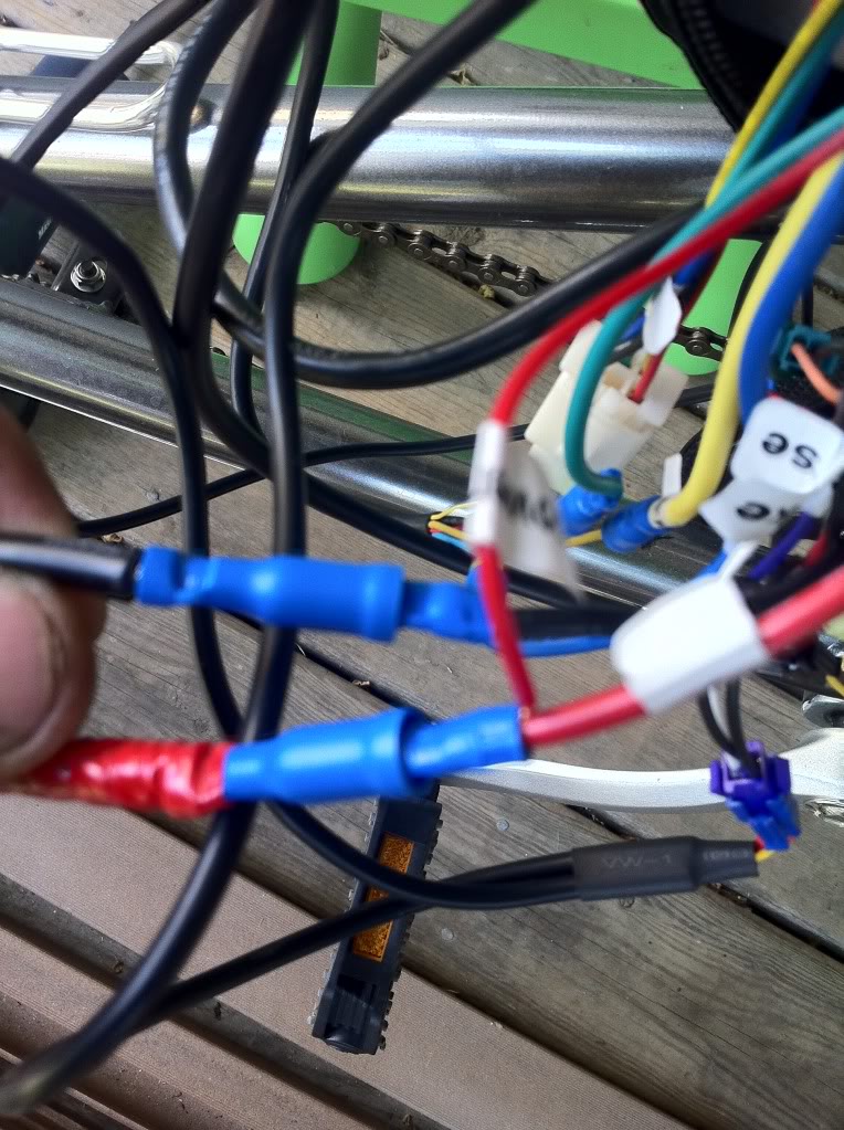
Slide a battery onto the rack. This can be very difficult the first time as it’s a no rattle plate and is very tight. Then plug in the battery and clean up all the wires by zip tying them neatly to the frame and collect all the slack wire together at the controller and tuck it neatly into the pouch.
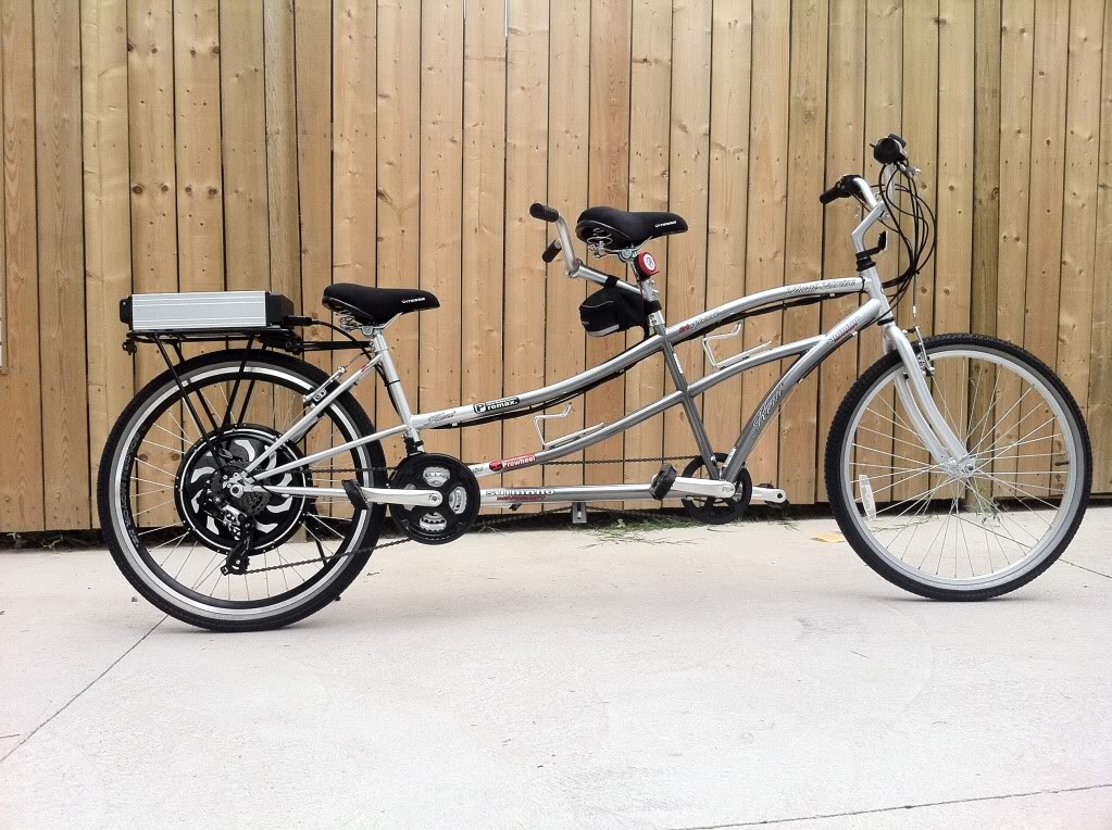
Now it’s done and ready for a test drive. I built this bike mainly for taking my daughter with us ebiking as she still is not confident on her own ebike. My son and wife both ride their own ebikes. We are quite the ebike family!
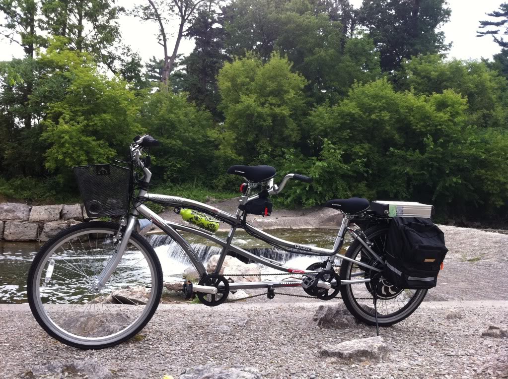
Added saddle bags and a front basket and Gone Fishing!
Gary


