OK is this correct?
Those 2 holes confuse me a little bit in the middle
one is to a brake and the other is for forward and reverse. Why I am confused about it is that there is just one pin for each, wouldn't there be a + and - for each.

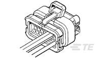
If I'd looked closer at the photo in the first place I would have realised the multiplug was different to the old controller. Even though it has 23 pins instead of the old 14 pin version, the -ve ground wires from the throttle, brake switch, reverse switch and hall sensors do not appear to connect through any of the multiplug pins, so they would need to be connected directly to the B- connection instead.
Hopefully this updated explanation of the HPC300A/500A controller connections will help:
Ref.
Page 2 of the User guide.(Motor wires are shown in bold)Screw terminal Connections B+ Battery Positive/Supply
(Heavy duty Red) B- Battery Negative/Ground
(Heavy Duty Black) U
Motor Phase Wire (Thick Blue) V
Motor Phase Wire (Thick Yellow) W
Motor Phase Wire (Thick Green)23 Pin Plug connections Pin 1 Controller Power on
(& Contactor coil energised) (Red) +ve feed from key switch
Pin 2
Not used Pin 3
Not used Pin 4
Not used Pin 5
Not used Pin 6
Not used Pin 7
Not used Pin 8 Contactor coil negative wire
Pin 9
Not used Pin 10
Not used Pin 11 Throttle Control 5V supply
(Red) Pin 12 Throttle Control Signal Wire
(White?) Pin 13 To Ground via Brake Switch
Pin 14
Motor Hall Sensor 5V Supply Wire (Thin Red) Pin 15
Not used Pin 16
Not used Pin 17
Not used Pin 18 To Ground via Fwd/Rev Switch
Pin 19
Not used Pin 20
Not used Pin 21
Motor Hall Sensor Wire (Thin Yellow) Pin 22
Motor Hall Sensor Wire (Thin Green) Pin 23
Motor Hall Sensor Wire (Thin Blue)Throttle, Brake switch, reverse switch and
Motor Hall Sensor Black leads must be grounded to B-.
Pin layout (As viewed from the cable side of the plug) (1)
(2) (3) (4) (5) (6) (7) (
8
)
(9) (10) (11) (12) (13) (14)
(15)
(16) (17) (18)
(19) (20) (21) (22) (23)

Plug Part No: 770680-1
Click
Here for more details.
I think these details are correct now.
 Alan
Alan