Author Topic: Smart Pie III REVERSE MODE setup Help ! (for a Wheel-Chair)  (Read 5131 times)

Offline Matteo555

  • Confirmed
  • New Member
  • *
  • Posts: 2
Smart Pie III REVERSE MODE setup Help ! (for a Wheel-Chair)
« on: December 05, 2019, 01:28:37 PM »
I apologize, I inverted the pinput cause male/female mistake, the picture now seems to be replaced with the correct one.
Need to set up a REVERSE MODE, from a old SMART PIE 3 with a new MP3 controller replaced because the old one got broken, so I had a new wire harness and need to a new set up. (for a WHEEL-CHAIR use)

I meant to connect C3 (blue wire/native reverse) to B4 (free yellow wire/Z pin free), B4 seems to be free and it match with A2 (free pin in plug A with free Z pin connection), so the plan was to connect B4 to A2 and then A2 (female) connected with M3 (male) that has soldered in HORN SWITCH, then, get a BATTERY GROUND - from M4, is this a possible connection (share cruise control and reverse battery ground- together) ?
Or it need also to connect C2 to B2 and then because B2 is matching with A1 (female) I can bring "native reverse" BATTERY GROUND- from A1 to M4 (HORN SWITCH) ??

Please a last question, I saw a throttle with 4 wires, black, green and white go to HALL sensor pins, then exist 1 more yellow wire that it seems to display the battery charge in numerical percentage, this yellow wire in the instructions seems to be connected to "bike positive pole", WHAT's this means ? yellow wire goes to BATTERY+ or LIGHTING FEED ??  --- WHAT LIGHTING FEED IS ??? (IS IT THE SWITCH ??)

THANKSSSSS
« Last Edit: December 06, 2019, 04:27:24 PM by Matteo555 »

Offline Bikemad

  • Global Moderator
  • Professor
  • PhD. Magic
  • ******
  • Posts: 5,553
Re: Smart Pie III REVERSE MODE setup Help ! (for a Wheel-Chair)
« Reply #1 on: December 06, 2019, 11:58:54 AM »
Hi Manuel andto the forum.

Here is the wiring layout for the MPIII, which should be the same as the Smart Pie III:
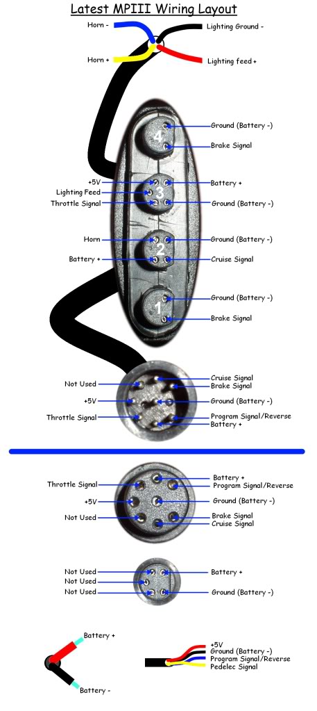


If your wiring is the same as the later MPIII/SPIII shown above do not connect C3 to B4, as the yellow wire (B4) will be supplied with full battery voltage when the horn button is pressed.

To activate reverse, you simply join the Blue and Black wires (C2 and C3) on cable "C" using a simple on/off switch.
If you want to use the switch mounted on the throttle unit, you may need to rewire the switch inside the throttle housing so that it switches the light feed to ground (instead of battery +) and then simply connect C3 to the B1 lighting feed wire to complete the reverse circuit.

The thumb throttle can be dismantled relatively easily to access the switch wiring (check out this post for more information) but the twist throttle is a bit more complicated to dismantle (Check out Tommycat's post on electricbike.com for full details).

I am somewhat puzzled by your description of the four pin plug (Plug "A") as you appear to have mirrored all of the connections (compared to the above diagram) and the horn switch would be unusable if there was "NO PIN" on connector A3.

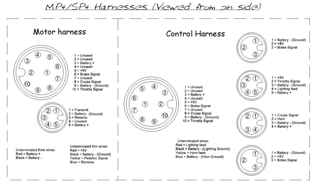
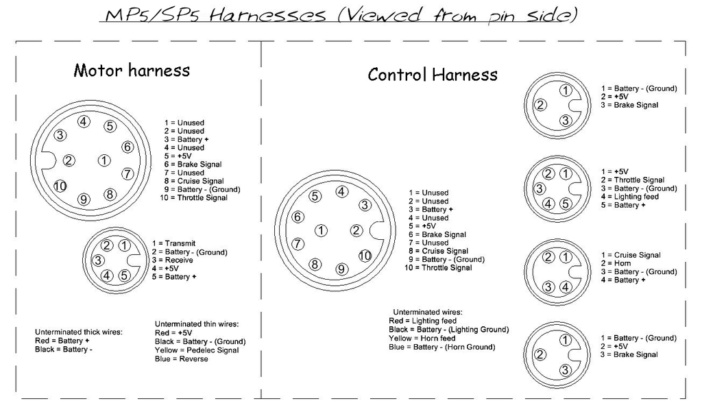
Regarding Plug "D" that is used for the speedometer display and USB programming cable on MP4 and MP5, on the MPIII harness that I tested when I drew the MPIII wiring layout diagram shown above, pins D2, D3 and D4 were not connected to any other wire on the harness and therefore could not be used for any purpose whatsoever.

On the MP4/SP4 harness this connector had the Transmit and Receive wires added:


The MP5/SP5 harness also added a +5V feed to this connector (presumably to power the Bluetooth dongle):


I seem to recall that some MPII harnesses were cofigured slightly differently at the factory to allow the throttle mounted switch to activate the reverse function instead of switching battery voltage to the LED light.

Alan
 

Offline Matteo555

  • Confirmed
  • New Member
  • *
  • Posts: 2
Re: Smart Pie III REVERSE MODE setup Help ! (for a Wheel-Chair)
« Reply #2 on: December 06, 2019, 10:55:31 PM »
Thanks very much for your reply, I didn't think to apply the reverse mode to the Throttle Switch, its a good idea, on my previous setup it was in the Horn Switch.

I want to make a correction on the picture that you sent, in 5 pin Female plug on MP3 Wire Harness, the battery+ is inverted with lighting feed, as shown in my picture, that's is real important thing for avoid a short circuit ! (I checked with tester).

Thanks anyway, I will try to find out the right setup.
Greetings