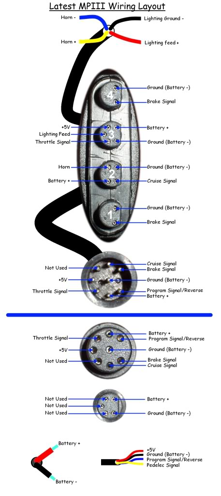
Here is the diagram for the earlier MPIII controllers with the 8 pin main connector:

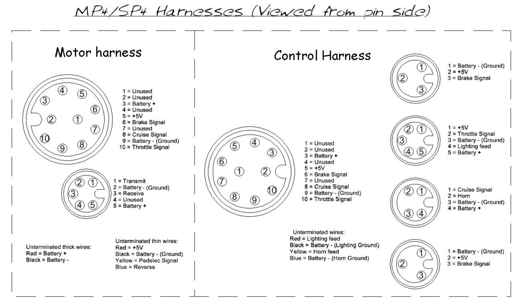
The later MPIII controllers had the 10 pin connector like the MP4 and MP5 as shown here:

To connect the MPIII to an external controller would need to extend the five Hall sensor wires and the three Phase wires from the motor to connect directly to the external controller.
If you could successfully desolder the Hall sensor socket from the dead controller, you could use this to connect to the motor's Hall sensor wires without having to change/remove the connector on the motor.


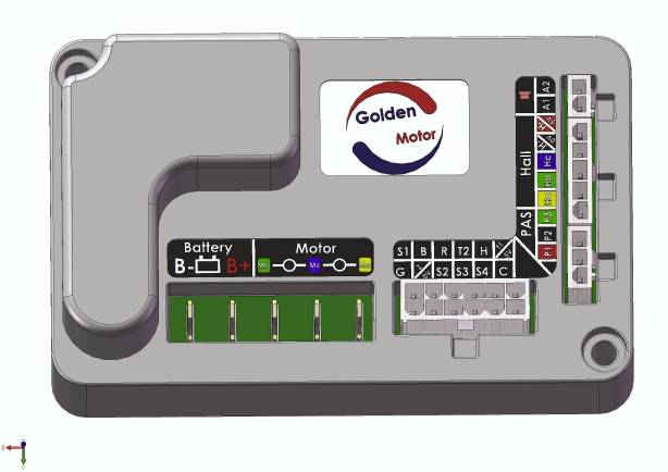
In the above diagram you would need to connect the following wires from the motor:
Mb Thick Green Phase wire
Mc Thick Blue Phase wire
Ma Thick Yellow Phase wire
Ha Yellow Hall sensor wire
Hb Green Hall sensor wire
Hc Blue Hall sensor wire
H-/0V Black hall sensor ground wire
H+/5V Red Hall sensor +5V feed wire
The old motor harness can be removed from the dead controller and then connected to the external controller connections as required, but make sure you make a note of the exact function of each colour wire attached to the old controller before you remove them.
You can use a multimeter with a continuity test function to confirm which colour wires are connected to each of the pins if you are unsure.
Connect the following wires from the old motor harness:
B- Thick Black battery positive wire
B+ Thick Red battery negative wire
and thin battery +ve wire
B Brake signal wire
R Reverse wire
T2 Throttle signal wire
H Horn wire
T1/5V +5V wire
Z/0V Thin battery -ve
(Ground wire)C Cruise control signal wire
Alan