Trying to explain how a mini geared hub actually works is not going to be very easy, but I'm going to do my best with the aid of these lovely photos that
Russell has conveniently posted on the Endless-Sphere forum, and I'm sure he won't mind his pictures being put to good use.

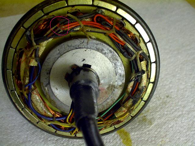
Let's start with the basics:
The stator
(containing windings and hall sensors) is permanently fixed to the axle and does not move.
The outer drum of the motor contains a ring of permanent magnets securely attached to its inner surface surrounding the stator.
This drum has a small gear attached to the opposite side
(see picture below) and the whole assembly is mounted to the axle by a bearing inside the gear, which allows the whole drum assembly to freely rotate around the fixed axle when power is applied to the windings via the controller.
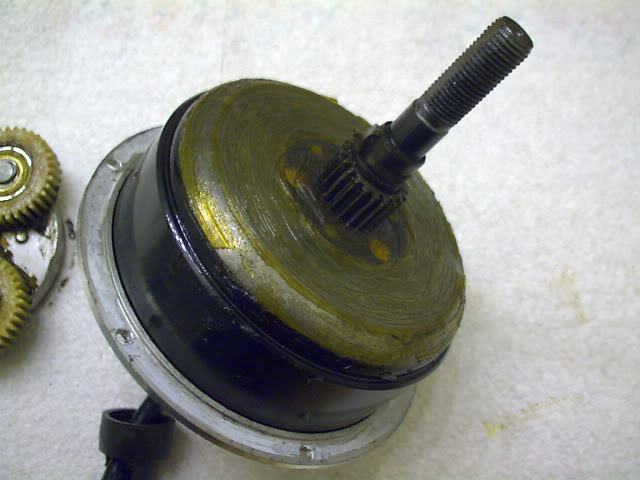
The stator, axle and drum assembly above make up the basic motor unit.
So we have a motor that can spin freely, but it still needs to transmit its power to the hub and produce enough torque to turn the wheel and drive the bike.
This is cleverly achieved by the use of an epicyclic gear train, which provides a gear reduction between the motor and the hub, which greatly increases the torque
(turning force) at the wheel.
The following two pictures show both sides of the intermediate gears
(known as the Planet Gears) which are driven by the motor's small gear (the Sun Gear) and are mounted on a unidirectional clutch
(a special type of ratchetless freewheel), which is secured onto the axle with a key and slot to prevent the centre piece from turning.
The clutch is very simple and comprises of three cylindrical rollers which are gently held by springs into the narrow end of a wedge shaped opening.
If the gear carrier in the first picture below is turned clockwise, it wedges the rollers between the carrier ring and the centre of the clutch, which effectively causes the carrier to become fixed in relation to the axle and will allow the rotational force to be transmitted between the motor and the hub.
This automatic locking action occurs whenever the motor tries to turn the wheel.
If the carrier is rotated the opposite way, the rollers will simply roll towards the larger end of the wedge shaped opening until the slight spring pressure prevents the friction from pushing the rollers any further.
As they are no longer wedged in, they are unable to transmit any load using the surface friction alone and the rollers will simply slip easily around the centre of the clutch, producing a noiseless and almost frictionless free-wheeling action.
This is how the hub manages to rotate easily, as it does so without having to turn against the resistance of the motor.
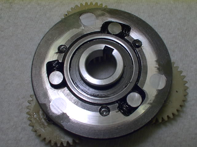
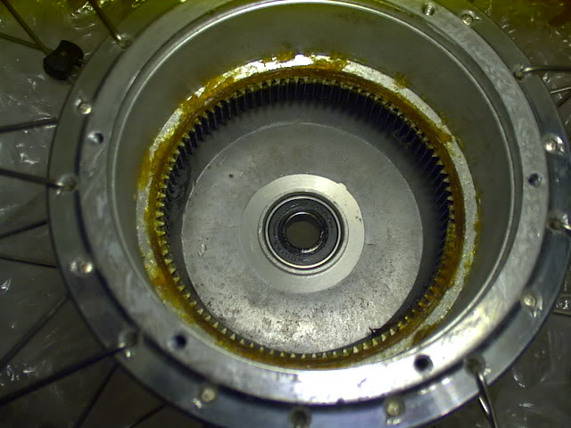
The picture below shows the side which faces towards the motor unit.
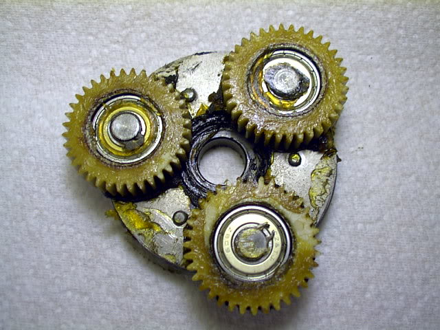
The outer gear
(Ring Gear) is permanently fixed to the inside of the hub, and this allows the drive to be transmitted to the hub itself.
Now have a look at the following diagram and imagine your looking at the wheel from the left hand side.
The small gear in the middle is the motor, which only rotates
clockwise when viewed from this side.
The three planet wheels are fixed to the carrier which is only free to rotate
anticlockwise, as it will be fixed in relation to the axle when the motor tries to turn it clockwise.
This allows the hub to be driven anticlockwise
(forward wheel rotation) by the motor.
If the motor is stopped and the wheel is moving in a forward direction, the hubs outer ring gear will try to turn the three planet gears anticlockwise around the
stationary sun gear
(it's stationary because the motor is stopped).
The free-wheeling action of the clutch allows the carrier to be freely turned in an anticlockwise direction with very little resistance.
So when you're pedalling without motor assistance, the planet gears will still be rotating, but as there is very little resistance, you're not usually aware of it.

The actual gear ratio is determined by the number of teeth on the sun wheel and the number of teeth on the ring gear.
So for example, if you had 9 teeth on the motor and 90 teeth on the hub you would have a 10:1 speed reduction and a 10x increase in torque!
Frank,
As Muzza and Russell have already mentioned, the motor will spin in reverse, but will not transmit any drive due to the unidirectional clutch in the centre of the gear carrier assembly, which is also why regen doesn't work with these motors.
If you were to fit the wheel backwards, the motor would not be able to drive the bike in a forward direction, but you should have very good regen!

It's just that it won't be much use as a hubmotor if you can only use it for going backwards and regen!
Alan