Author Topic: Hub Motor Questions, Hall Elements etc.  (Read 2875 times)

Offline Acond

  • Confirmed
  • New Member
  • *
  • Posts: 10
Hub Motor Questions, Hall Elements etc.
« on: June 29, 2021, 06:39:37 PM »
Hello all and Regards from Finland!

So, new here, hope to get cooperation with you in the future. Nice to find this forum.

I am working with geared e-bike hub motor which does not work. The other parts of the bike are ok as with another (same trade) hub motor it works. I got the link to this forum from the "guide":
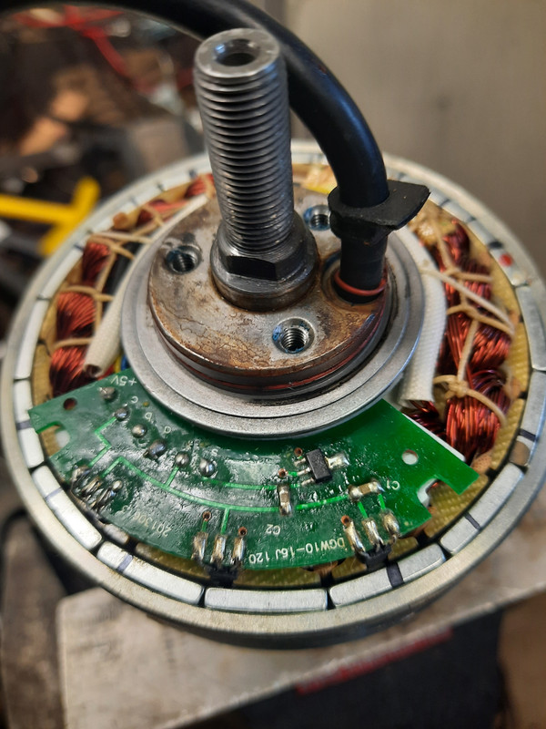
https://www.instructables.com/Electric-Bike-Hub-Motor---How-to-Replace-a-Hall-ef/

My construction has 16 permanent magnets in rotor and 18 poles in stator. Figure is enclosed. Magnets are N-S-N-S etc. as expected. Three Hall elements (41F 402) are built in between stator poles. Black cable has 9 pins; three thick pins for 3 phase AC-motor stator and 6 thin pins as follows: 5V input for Halls, ground, four outputs of which three comes from the mentioned 41F 402 Hall-elements (marked a,b and c) and the fourth comes from the component which I do not know what it is but let's come back to that later. When I feed from my power source 4.7V in and rotate the motor I can see that a-hall gives out 4.2V when facing S-pole and 0V when facing N-pole. So I believe that it works like it should. The b-Hall gives 2.3V/0V respectively. The c-Hall is more crazy. It gives 3V when facing N-pole and 4.3V when facing S-pole! I believe that all Halls should work in the same way...

1. Is it so? My idea is to change them all. If you agree could I use SS 41 elements (which I already have) or should I use original 41F version which according to data sheet are called (more) sensitive.
2. Do you have any idea what is the component which I do not know. It is rectangular, located between C1 and C2; slightly above them and having three legs to left and one to right. It is fed from this 5V pin, center is earth (like the leg in right side) and the last leg is some kind of output as that goes to the fourth pin in the black cable. There is a small round permanent magnet in the hub which passes this component every wheel round. The N-pole of this small magnet is against this strange component. Do you have any idea what it is. I cannot read any out put Voltage from it when rotating the wheel.

This bike is Swedish made under OFF COURSE -Trade Mark, power supply bat is 36V. Hope to get your comments and help to this case.


« Last Edit: June 29, 2021, 07:13:07 PM by Acond »

Offline Acond

  • Confirmed
  • New Member
  • *
  • Posts: 10
Re: Hub Motor Questions, Hall Elements etc.
« Reply #1 on: June 29, 2021, 06:47:23 PM »
Hello all and Regards from Finland!

Forgot to mention that stator wiring is OK, tested it by short circuiting them in pairs and tried to rotate, load increased ...[/b][/u]


« Last Edit: June 29, 2021, 07:13:19 PM by Acond »

Offline Bikemad

  • Global Moderator
  • Professor
  • PhD. Magic
  • ******
  • Posts: 5,507
Re: Hub Motor Questions, Hall Elements etc.
« Reply #2 on: June 30, 2021, 12:32:48 PM »
Hi andto the forum.

I would also expect all three sensors to behave the same (alternating between ~4.2V and 0V).

I would change all three existing sensors for the SS41 Hall sensors (that you already have) and see if the motor then works again, as SS41 sensors are typically used on various makes of hubmotors as replacements.

The rectangular component looks like a surface mount transistor to me, but I suppose it could be some form of Hall Effect sensor in a similar package as there does not appear to be an obvious inductor or reed switch etc. to sense the passing of the magnet, which I suspect is used by the controller to measure the rotational speed of the hub to cut the power to the motor when the maximum legal motor assist speed is reached.

Alan
 

Offline Acond

  • Confirmed
  • New Member
  • *
  • Posts: 10
Re: Hub Motor Questions, Hall Elements etc.
« Reply #3 on: June 30, 2021, 04:36:59 PM »
Hello Bikemad

..and thanks for your quick reply. I'll put 3 pc of new SS41 Halls there. Then it is easy to test. Let's see.

The squared component can be a Hall. What I wonder here is that the N-pole of magnet goes close to it not South which is normal for unipolar Hall-elements if I understood this right. South activates both unipolar and bepolar, bepolar requires North to "open" while with unipolar it is enough that you just move the magnet far away enough. This is now something I do not understand. Have to try to read the markings of that component with microscope. There is some text.

Then there is another question. I read here in this forum that modenrn control systems do not need these Hall-elements anymore to control the motor. Did I undestand it in the right way. How do they work. How do they analyze the motor movement? From stator currents or what. Where I could find info about this?


Offline Tommycat

  • Confirmed
  • Bachelor of Magic
  • ****
  • Posts: 178
Re: Hub Motor Questions, Hall Elements etc.
« Reply #4 on: June 30, 2021, 05:31:36 PM »
Hold on… was the hall sensor testing done with out the controller connected? If so, and without a pull-up resistor used. Erratic readings may result.


Regards,
T.C.
See my completed Magic Pie V5 rear hub E-Bike build  HERE.

Offline Acond

  • Confirmed
  • New Member
  • *
  • Posts: 10
Re: Hub Motor Questions, Hall Elements etc.
« Reply #5 on: June 30, 2021, 05:43:16 PM »
I was lazy, just the motor on the table, 4.7V in and no pull-up resistor.

Offline Acond

  • Confirmed
  • New Member
  • *
  • Posts: 10
Re: Hub Motor Questions, Hall Elements etc.
« Reply #6 on: June 30, 2021, 06:25:19 PM »
I could put a 10k resistor there and re make the measurement.

Offline Tommycat

  • Confirmed
  • Bachelor of Magic
  • ****
  • Posts: 178
Re: Hub Motor Questions, Hall Elements etc.
« Reply #7 on: June 30, 2021, 08:03:00 PM »
I would certainly recommend making a proper check of them first.

A bench test would look like this...


For complete details on checking the halls, with or without a controller. Checking the phase windings, and halls to phase wiring configuration, see this thread where the above diagram came from...

Testing BLDC motor's Phase Wiring - Hall Sensors and Wiring.

See my completed Magic Pie V5 rear hub E-Bike build  HERE.

Offline Acond

  • Confirmed
  • New Member
  • *
  • Posts: 10
Re: Hub Motor Questions, Hall Elements etc.
« Reply #8 on: July 01, 2021, 07:15:13 AM »
Sure, thanks. I made it that way tonight and report back. Good to have professionals around...

Offline Acond

  • Confirmed
  • New Member
  • *
  • Posts: 10
Re: Hub Motor Questions, Hall Elements etc.
« Reply #9 on: July 01, 2021, 02:24:47 PM »
Strange!
I did not know that pull-up resistor is that essential here. Doing measurement as you advised the result was:
Hall a 5/0
Hall b 5/0
Hall c 5 all the time (broken?)
Squared component which I did not recognize gave 5/0  that "zero" happens once/wheel round.

And what also happened my power source started to give 5V when this pull-up resistor was connected. I was wondering why it was less without any load. So this is perhaps quite clear, have to renew Hall c (or all three just for sure).

Thanks again Tommycat!


Offline Tommycat

  • Confirmed
  • Bachelor of Magic
  • ****
  • Posts: 178
Re: Hub Motor Questions, Hall Elements etc.
« Reply #10 on: July 02, 2021, 02:34:41 PM »
Hall c 5 all the time (broken?)

So this is perhaps quite clear, have to renew Hall c

Your certainly close if not there...
As a final check with your testing set-up in place, I would recommend taking voltage checks at the hall sensor "C" legs. With your black meter test lead on the middle leg (ground), test the other two side legs... you should get 5vdc on both. This would eliminate any problems on the hall sensor PCB board or connections, leaving the sensor itself as the lone problem.


Squared component which I did not recognize gave 5/0  that "zero" happens once/wheel round.

Well done on providing that last RPM sensor with a reference voltage to check it's operation! Good catch. I'll have to add that information to my thread.  :) If you happen to get the information on that sensor, I'll put it to use.  ;) EDIT: Last question, what color wire was used for the RPM sensor line?

Glad to help. Cheers!


« Last Edit: July 02, 2021, 09:00:39 PM by Tommycat »
See my completed Magic Pie V5 rear hub E-Bike build  HERE.

Offline Acond

  • Confirmed
  • New Member
  • *
  • Posts: 10
Re: Hub Motor Questions, Hall Elements etc.
« Reply #11 on: July 04, 2021, 07:58:20 AM »
Hello, I continue as you proposed and inform everything I find. The motor is not here where I am now. I inform also the colours if they can be seen. I also made a map which pin is which wire to make it easier to study the case without dissassembling the motor. So, end of this week...

Offline Acond

  • Confirmed
  • New Member
  • *
  • Posts: 10
Re: Hub Motor Questions, Hall Elements etc.
« Reply #12 on: July 08, 2021, 05:19:42 PM »
Decided to change only Hall c to see whether the motor start to work as measurement of all three Halls look now similar. If it works I change perhaps the other two, too. What do you think? I made also a map of my motor cable plug pins. This cable comes from motor and is Male Side. (Female plug comes from controller).

Motor side plug is drawn on the top. In 9.00, 12.00 and 3.00 are the thick pins for stator. Then there are six thin pins:
10.30, Hall a output
7.30, Hall c output
6.00, Hall b output
4.30, +5V (in)
1.30, S=output of the rectangular rev counter component which I do not know what it is.
In the center is ground. Below that is the location of hall elements c, b and a from left to right and info of pins. Center pin is ground.
Unfortunately it is not possible to see which color is the S wire. I can see only five coloured wires and it is not possible to see where they go. If I have to take the printed card away later I can report the colors.
I tried to make some figures of the text printed in the rectangular component. I put them here later. I can just guess what there is written.

Offline Tommycat

  • Confirmed
  • Bachelor of Magic
  • ****
  • Posts: 178
Re: Hub Motor Questions, Hall Elements etc.
« Reply #13 on: July 08, 2021, 08:39:40 PM »
Decided to change only Hall c to see whether the motor start to work as measurement of all three Halls look now similar. If it works I change perhaps the other two, too. What do you think?

My opinion would be to leave well enough alone, unless there are other unknown factors. Such as known excessive heat, water, or voltage damage?
Your skill at de-soldering/soldering would also be a factor.

No worries about the wire color.

I hope the motor test goes well!  :)


See my completed Magic Pie V5 rear hub E-Bike build  HERE.

Offline Acond

  • Confirmed
  • New Member
  • *
  • Posts: 10
Re: Hub Motor Questions, Hall Elements etc.
« Reply #14 on: July 09, 2021, 11:01:08 AM »
It works! Thanks for your professional help.