Author Topic: I'm almost there! Just a few more questions before my bike is built.  (Read 16637 times)

Offline Wilson_wu

  • Confirmed
  • Junior Member
  • **
  • Posts: 29
1) Wire from the battery to the bike
I also noticed the wire coming from the battery is sized AWG 14, while the wire coming from the bike is AWG 10 (or 12, not sure, don't remember)...is there going to be any compatibility problems?

Can I even connect these two wires? If yes, any suggestions as to how to connect the two? Soldering or an easier way to connect the two?

Will the thinner 14AWG wire affect the amps that the Golden Motor needs to run? People online say 14AWG wires can only run 15amps max. Yet, why does the Bioenno Battery Specs says its Maximum Discharge Current is "30A". Is this a contradiction or am I just not understanding? :( I'm freaking out as this battery was extremely expensive and there's probably no return on it. What amps would my 36V Golden Motor Magic Pie 5 need to run?

2) The pedelec
I understand the installing the 2 pieces to the crank part. But how do you actually connect the pedelec pieces to the bike? And then
 there's a cord with 3 exposed wires coming out of it.

3) I ordered a USB cable.
My USB cable didn't come in my package. I've checked everywhere, I'll check again tomorrow but I'm fairly certain I didn't receive it. I've received everything else but that. Is the USB cable already on the bike and I just don't know it? Does it come packaged separately from everything else or is it preinstalled like all the wires were. I've ziptied all the wires down to the frame already.

 Also, is the USB cable supposed to connect in the same area as the Bluetooth Dongle?
« Last Edit: May 18, 2017, 07:37:18 AM by Wilson_wu »

Offline Bikemad

  • Global Moderator
  • Professor
  • PhD. Magic
  • ******
  • Posts: 5,510
Hi Wilson,

1) Wire from the battery to the bike

Your battery should have come complete with the 50A Anderson connector as clearly shown and stated:


Quote from: www.bioennopower.com
Charge Connector:  Anderson Power Pole
Discharge Connector:  Anderson Power Pole
Charger Connector:  Anderson Power Pole (50A)

If it was not supplied as described, you will have to contact your battery supplier for a solution.

The battery wires used by the battery manufacturer should be capable of supplying their stated current:
Quote from: www.bioennopower.com
Maximum Continuous Discharge Current: 30A (Make sure your load consumes less than 30A)

The Magic Pie should be set to 25A maximum by default, which is obviously less than 30A, so this should not cause a problem with the thinner battery wires, but I suggest that you check that the thinner battery wires do not get too warm under continuous high current use.

Do not solder the battery wires directly to the motor wires, as you will need to disconnect them when the bike is not being used to prevent the battery from being slowly discharged.
You may also want to remove the battery to allow it to be recharged indoors, especially if your bike is kept outside in an unpowered garage/shed etc.

You can solder the motor wires to the contacts in the Anderson connectors so that it can simply plug into the battery connector (assuming the battery was supplied as described).

2) The pedelec
The pedelec sensor bracket fixes onto the bottom bracket assembly and the magnet ring slips over the bottom bracket pedal shaft. I simply removed the lock ring, and secured the sensor using the lock ring to hold it in place:


The Black, Red and Green wires at the end of the pedelec sensor cable need to connect to the Black, Red and Yellow wires in the pedelec/reverse cable on the motor's wiring harness:


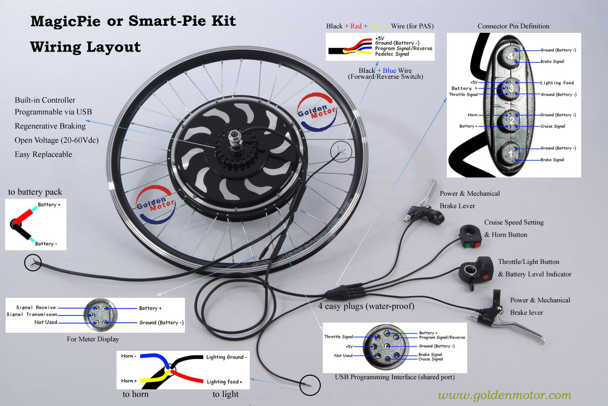
These wires can either be soldered directly to the respective wires, or you can fit a suitable 3 pin inline connector to allow the rear wheel to be removed more easily to replace inner tubes or tyres etc.
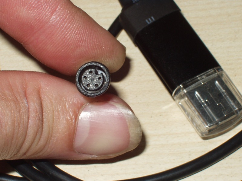
3) USB cable

The USB programming cable is a separate unit, and is usually supplied separately.
If you have definitely not received it, contact your supplier and explain the shortage to them.

Yes, the USB cable connects to the same 5 pin connector as the Bluetooth dongle (and the BAC-601 Smart LCD Display unit) but only one device can be connected at a time:


Hopefully you will soon have you bike all sorted and ready to use.


Alan
 
« Last Edit: July 04, 2017, 11:10:27 PM by Bikemad »

Offline Wilson_wu

  • Confirmed
  • Junior Member
  • **
  • Posts: 29
Quote
Don't worry. 30A is the maximum possible current the battery can put out.
For most applications you typically won't pull the maximum current draw
off the battery - if you bike does pull an average of 30A we would have
recommended a bigger battery.

This was the official response from Bioenno Power. Is it true that 14AWG wires should not have more than 15amps of current running through them for an extended amount of time? Isn't the Golden Motors average continuous output higher than that?
« Last Edit: May 18, 2017, 07:26:07 PM by Wilson_wu »

Offline Bikemad

  • Global Moderator
  • Professor
  • PhD. Magic
  • ******
  • Posts: 5,510
Quote
Don't worry. 30A is the maximum possible current the battery can put out.

Perhaps they should update their specifications:

Quote from: BLF-3630V_User_Manual_rev_08_12_2016.pdf
Maximum Continuous Discharge Current 30A
Maximum Peak Pulse Current 60A (2 sec.)

Although it's only for 2 seconds, as far as I am aware, 60A is still more than 30A!

Is it true that 14AWG wires should not have more than 15amps of current running through them for an extended amount of time? Isn't the Golden Motors average continuous output higher than that?

Unfortunately it is not quite that simple, as it also depends upon how efficient it needs to be, and how acceptable the voltage drop across the wire is.

14 gauge wire would probably cope with up to 55 Amps continuously, but at this level of current it would need sufficient airflow to cool the wire and prevent it from becoming too hot.

The main problem with using thinner gauge wire is its higher resistance, and the higher the resistance, the greater the voltage drop per length of wire.
This voltage drop can be significant with longer lengths of thinner gauge wire carrying higher currents, and this also results in energy being wasted in the form of unwanted heat in the wires.

It's very difficult to say what the average current draw would be on a Magic Pie as it is dependent upon many variables, including speed, weight, headwinds, inclines, and the amount of pedal assistance being provided by the rider.

Here's an extreme example:
I went for a 13.6 mile cycle ride last weekend using a Magic Pie, the route was pretty level and I was only riding at an average speed of around 10 mph (fast enough to keep up with the wife on her non-electric bike) and the trip was predominantly leg powered rather than motor powered.
The motor consumed a total of 0.826Ah from my battery, which equates to an average constant current of just 0.583 of an Amp over the 1hr 25min long trip!

I did say it was an extreme example.  ;)

Alan
 

Offline Kneedeep

  • Confirmed
  • Junior Member
  • **
  • Posts: 37
You don't need to run the pie maxed out either. I run mine at 20A on the controller and me and my bike combine a weight of 322lb I also still turned rpm down to legal speeds. My key switch for the bike is running 14awg wire for 5" either side of the switch with no issues and no heat.

Offline Wilson_wu

  • Confirmed
  • Junior Member
  • **
  • Posts: 29
Thanks Bikemad.

Im in the process of buying a crimping tool and some butt connectors...off the top of your head, do you know what gauge the black/red/yellow wires were? They're very thin. 20AWG or so? Do you know precisely?

Offline Bikemad

  • Global Moderator
  • Professor
  • PhD. Magic
  • ******
  • Posts: 5,510
Unfortunately, I couldn't measure the wire accurately enough to determine whether it is 20 AWG or 21 AWG.  :-\

Alan
 

Offline Wilson_wu

  • Confirmed
  • Junior Member
  • **
  • Posts: 29
I keep pushing the idea of a return to the battery company and they keep just dismissing my concerns.

I'll give the battery a shot. But I'm realizing now the Anderson SB50/SB50A is not compatible with 14AWG wires. At least Im not seeing the results when I google it.

I have no idea how to connect a 14AWG wire to a 10AWG wire with an easy-to-disconnect connection? Any ideas?!

Offline Bikemad

  • Global Moderator
  • Professor
  • PhD. Magic
  • ******
  • Posts: 5,510
Hi Wilson,

Returning a battery can be very problematic as they are classified as dangerous goods, and it can be very difficult to find a means of returning the battery without spending a fortune, or breaking the law.

The SB50 connector can accept wires as thin as 16 AWG:


Unfortunately, they also have several different contacts with different hole diameters to suit different wire sizes:


If your connectors have the large holes and you are using smaller diameter wires, this may be a problem if you were crimping the wires with the extortionately priced Anderson crimping tool, but most DIY users tend to solder the wires into the contacts using extra solder to completely fill any gaps between the wire and the contact.

If you are lucky enough to have access to the correct crimping tool, you could stip the insulation away on a longer portion of the thinner gauge wire and the fold the exposed copper over on itself to make it twice as thick (or even add additional wire if necessary) to fill the hole before crimping.  ;)

If your battery supplier cannot supply you with a matching connector to suit the one on the battery, then the Anderson connectors should provide a good reliable battery connection.

Another alternative is to use the much smaller "T" connectors which are commonly used on R/C models as these will easily carry the 30A maximum current:


Click the above picture to see eBay listing.

You would also need some suitable heat shrink tubing to safely insulate the soldered joints:


I have used these style connectors for many years and they seem to work very well on my eBikes.

The male connector with exposed contacts is soldered to the controller's power wires and the female connector with the enclosed contacts is used on the battery wires.

Alan
 
« Last Edit: July 01, 2017, 11:12:28 PM by Bikemad »

Offline Wilson_wu

  • Confirmed
  • Junior Member
  • **
  • Posts: 29


I seemed to have accidentally yanked out the yellow wire in this one. Is this a standard piece I can buy somewhere? What is it called?

What is the purpose of the white plug that connects the green/red/black wires to the yellow/red/black wires? Is it simply for ease of detachment? Can I not just snip these off and simply connect the green/red/black wires coming out of the pedelec sensor to the yellow/red/black wires coming out of the motor with a butt connector?
-----

Also I submitted a ticket about the USB cable I never received, I received a response but their ticket support system has been down for 2 days. GM Canada, any idea when this will be back up?

----

Do I even need the USB cable to set up my system or can I use my Bluetooth dongle to set up my ebike? Or is the USB cable absolutely required?
« Last Edit: May 31, 2017, 09:47:37 PM by Wilson_wu »

Offline Bikemad

  • Global Moderator
  • Professor
  • PhD. Magic
  • ******
  • Posts: 5,510
Re: I'm almost there! Just a few more questions before my bike is built.
« Reply #10 on: May 31, 2017, 10:49:30 PM »
I'm not sure what type of connector that is, but I was unable to find an exact match for that connector the last time I looked.

The connector makes it easier to remove the wheel, but you can remove the connector and use a different type of connector, or solder the wires directly if you want to.

I would email Gary (garysalo@goldenmotor.ca) or open another ticket, as Gary was having problems with the old ticket system and recently had to install a whole new version of it. If your ticket was created with the old system, there's a chance that it might not be recognised by the new system.

If you have a compatible phone that works with the Bluetooth Dongle, then you should be able to alter all the available controller settings via the Bluetooth App.

Alan
 

Offline Wilson_wu

  • Confirmed
  • Junior Member
  • **
  • Posts: 29
Re: I'm almost there! Just a few more questions before my bike is built.
« Reply #11 on: May 31, 2017, 11:23:56 PM »
I'm not sure what type of connector that is, but I was unable to find an exact match for that connector the last time I looked.

The connector makes it easier to remove the wheel, but you can remove the connector and use a different type of connector, or solder the wires directly if you want to.

I would email Gary (garysalo@goldenmotor.ca) or open another ticket, as Gary was having problems with the old ticket system and recently had to install a whole new version of it. If your ticket was created with the old system, there's a chance that it might not be recognised by the new system.

If you have a compatible phone that works with the Bluetooth Dongle, then you should be able to alter all the available controller settings via the Bluetooth App.

Alan

Thanks...just to make sure...I can solder the green wire to the yellow wire? Thanks!

Offline Bikemad

  • Global Moderator
  • Professor
  • PhD. Magic
  • ******
  • Posts: 5,510
Re: I'm almost there! Just a few more questions before my bike is built.
« Reply #12 on: June 01, 2017, 09:20:36 AM »
Thanks...just to make sure...I can solder the green wire to the yellow wire?

Yes, solder Red to Red, Black to Black and Green to Yellow and then carefully insulate them from each other and try and make the joint as waterproof as possible.

Alan
 

Offline GM Canada

  • Super Gary
  • Confirmed
  • PhD. Magic
  • ******
  • Posts: 1,544
Re: I'm almost there! Just a few more questions before my bike is built.
« Reply #13 on: June 01, 2017, 02:41:06 PM »
Sorry you are having this problem.

The old ticket system I can still access offline but I had to move on to a much newer updated system. The problem is people are clicking on old links in their email and being directed into the old system and its been taken offline. If you are having an issue just create a new ticket and I can go into the old system if necessary and dig out any details.

Gary

Offline Wilson_wu

  • Confirmed
  • Junior Member
  • **
  • Posts: 29
Re: I'm almost there! Just a few more questions before my bike is built.
« Reply #14 on: June 04, 2017, 05:02:01 AM »


Take a look at this beauty! There's something SO rewarding about putting something together yourself as opposed to just buying it off the shelf. Prior to this, the only time I've probably ever touched a tool was to tighten a loose screw or something.

The box sitting on the front of the bike, I drilled two holes into it so I could fit and hide my wires inside the thing! :D You can barely see the wiring for the ebike!

I really wish the Magic Pie 5 came in a fully black rim version. The Black Pie 5 sadly also has silver in its rim brake area.

Thanks for everything and everyone. And my questions that probably made you guys want to bash your heads on your keyboards. :(
« Last Edit: June 04, 2017, 05:04:39 AM by Wilson_wu »