Author Topic: HPM5000B 48V hall sensor problem  (Read 11433 times)

Offline The Grey

  • Confirmed
  • New Member
  • *
  • Posts: 7
HPM5000B 48V hall sensor problem
« on: January 09, 2013, 11:23:12 AM »
Hey everybody,

I recently purchased a HPM5000B 48V 5kW motor from GM (Brushless).
This one has intergrated hall sensors. So I hooked it up to 5V and took a look at the phases. Turns out that none of the voltages change when I'm moving the axis of the motor. I read somewhere that, that would mean the hall sensors are broken!
I find the chance very small, since the motor is brand new!

My setup is:
5V+ at the red wire, ground at the black wire and I used a multimeter to measure all the phases individually.
I also tried a pull down resistor, but it didn't work...

Does anyone knows what I'm doing wrong?
Or how to check the hall sensor is really broken?

Thanks a lot!
Kind regards,
The Grey

Offline MAGICPIE3FOCUSPOWER

  • Confirmed
  • Master of Magic
  • *****
  • Posts: 372
Re: HPM5000B 48V hall sensor problem
« Reply #1 on: January 09, 2013, 05:37:09 PM »
Just hook up an external 4-5 V power suplly to red and black wires of the hall sensor connector.

Measure with a multimeter between red wire and the three hall sensors wires.
When turning the wheel the voltage should change 0V or 5V

Offline The Grey

  • Confirmed
  • New Member
  • *
  • Posts: 7
Re: HPM5000B 48V hall sensor problem
« Reply #2 on: January 09, 2013, 08:24:17 PM »
I exactly did that, but the voltages did not change!
Any other suggestions?
If you want to I can draw a connection schematic!

Thanks!

Offline MAGICPIE3FOCUSPOWER

  • Confirmed
  • Master of Magic
  • *****
  • Posts: 372
Re: HPM5000B 48V hall sensor problem
« Reply #3 on: January 09, 2013, 10:52:19 PM »
Hmm sounds not good!

You can even try to open the motor and direct at the sensors.
Or there is some cable break?

Offline The Grey

  • Confirmed
  • New Member
  • *
  • Posts: 7
Re: HPM5000B 48V hall sensor problem
« Reply #4 on: January 10, 2013, 11:59:05 AM »
As far as I can see there is no cable break.
I currently don't have the tools to open it up.
So I went back to some testing.
Turns out that the voltages do change! Only in most cases it is 0,0 v - one step more - 3,8v-4,0v

Can someone (if they want to and can) give me some information about when one phase is high, how it gets high (one step or is it going by 0,1v per step or anything). And how the phases relate to each other?

Thanks alot!!

Offline MAGICPIE3FOCUSPOWER

  • Confirmed
  • Master of Magic
  • *****
  • Posts: 372
Re: HPM5000B 48V hall sensor problem
« Reply #5 on: January 10, 2013, 12:39:56 PM »
Sounds the hall sensors are good:-)

But what is the problem? motor is not running?

Offline Bikemad

  • Global Moderator
  • Professor
  • PhD. Magic
  • ******
  • Posts: 5,510
Re: HPM5000B 48V hall sensor problem
« Reply #6 on: January 10, 2013, 03:57:41 PM »
Can someone (if they want to and can) give me some information about when one phase is high, how it gets high (one step or is it going by 0,1v per step or anything). And how the phases relate to each other?

The hall sensors used on the motors are not linear like a throttle hall sensor, so they are either in a fully open state or in fully closed state.
Check out this video to see the difference.

The three motor phase wires are all joined together at one end to form a star (Wye or "Y") configuration as shown here:


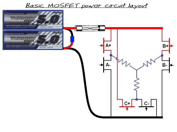
The remaining ends of the three phase wires are intermittently switched (independently of each other) using MOSFETs to select either battery positive or battery negative, according to the open or closed state of the hall sensor associated with each particular phase wire.

In order to adjust the power and speed of the motor, the MOSFETs are controlled by a throttle related variable pulsed signal (PWM), which basically regulates the effective voltage being supplied to the windings.


Check out the animation half way down the page on this website to see how the phase switching sequence operates on a typical three phase motor.

Alan
 
EDIT: Animation added because the interactive version on elabz.com is no longer working  :(
« Last Edit: July 20, 2020, 09:07:13 PM by Bikemad »

Offline The Grey

  • Confirmed
  • New Member
  • *
  • Posts: 7
Re: HPM5000B 48V hall sensor problem
« Reply #7 on: January 11, 2013, 08:25:57 AM »
Ah, I didn't know the hall sensors weren't linear!

Does anyone have the running sequence of the motor? Like Ahigh Blow *HallsensorA high* -> Chigh Blow ect...

I'm gonna read trough the link in the afternoon!
Thanks alot everyone!

Offline MAGICPIE3FOCUSPOWER

  • Confirmed
  • Master of Magic
  • *****
  • Posts: 372
Re: HPM5000B 48V hall sensor problem
« Reply #8 on: January 11, 2013, 05:52:10 PM »
I don't know the sequence.
Just test each sensor, if they work it's fine you are fine.


So you don't have to worry about the sequence.

Offline The Grey

  • Confirmed
  • New Member
  • *
  • Posts: 7
Re: HPM5000B 48V hall sensor problem
« Reply #9 on: January 12, 2013, 08:17:01 AM »
Well, I'm building a controller. So it would be handy  ;D

Offline MAGICPIE3FOCUSPOWER

  • Confirmed
  • Master of Magic
  • *****
  • Posts: 372
Re: HPM5000B 48V hall sensor problem
« Reply #10 on: January 12, 2013, 07:31:45 PM »
Aaha nice!

Maybe a mail to GM?

Offline The Grey

  • Confirmed
  • New Member
  • *
  • Posts: 7
Re: HPM5000B 48V hall sensor problem
« Reply #11 on: January 14, 2013, 08:30:00 AM »
I already mailed them three times, still no response....

Offline Morgen 3Eman

  • Confirmed
  • PhD. Magic
  • ******
  • Posts: 620
Re: HPM5000B 48V hall sensor problem
« Reply #12 on: January 14, 2013, 08:04:22 PM »
It would seem that the sequence A,B,C would be a logical assumption. 

TTFN,
Dennis

Offline The Grey

  • Confirmed
  • New Member
  • *
  • Posts: 7
Re: HPM5000B 48V hall sensor problem
« Reply #13 on: January 17, 2013, 08:43:35 AM »
I understand that. What I meant was, when A is high, does the phase Bhigh and Clow be activated or some other?

Offline MAGICPIE3FOCUSPOWER

  • Confirmed
  • Master of Magic
  • *****
  • Posts: 372
Re: HPM5000B 48V hall sensor problem
« Reply #14 on: January 17, 2013, 10:39:09 AM »
Maybe you should make your own hall tester with led?
So you can see when they lit when turning the wheel?

Just attached led and small reisistor at hall sensor output.