Hi Marek and

to the forum.
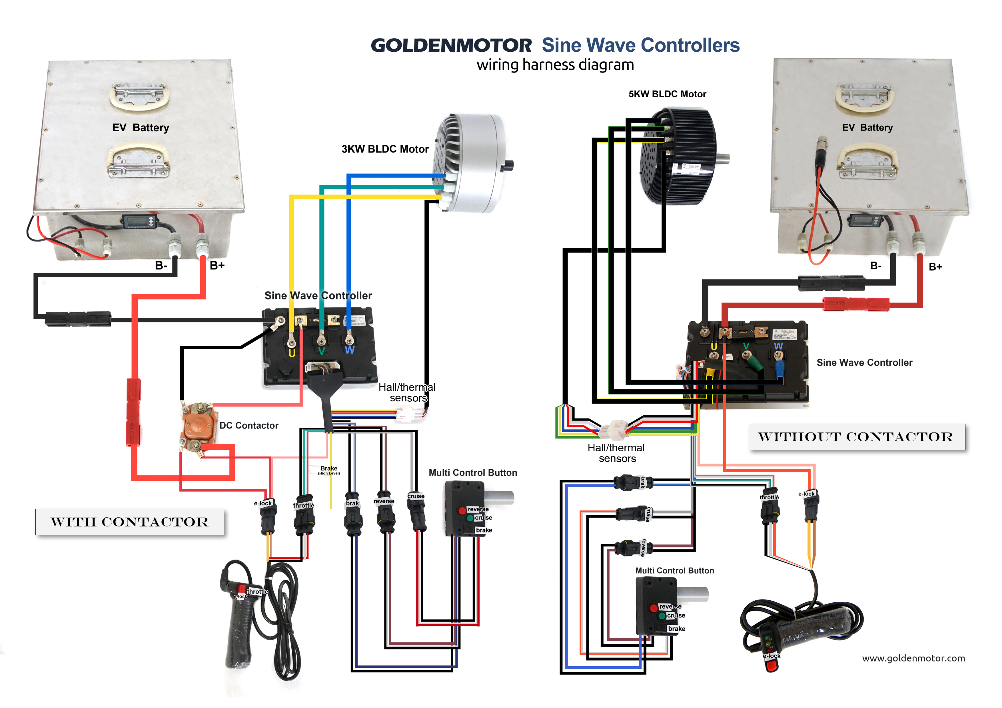
The wiring for the 3kW BLDC motor and controller should be relatively simple:

Unfortunately, none of the diagrams show details relating to the
connections required for the 3 position speed switch.
If you are wiring your controller via a contactor, check out
this post regarding my concerns over the e-lock connections shown on the above wiring diagram.
The connections between the motor and the controller should be straightforward but the throttle and switches are not very well documented.
The throttle uses three wires
(+5V [Red&White], Ground [Black&White] and Throttle Signal [Green&White]), and these wire connect to either a potentiometer or Hall Sensor type throttle.
The e-lock wires can be connected to a simple latching On/Off switch
(a key switch can alternatively be used for additional security).
The Brake wires connect to a momentary switch connected to the brake pedal
(contacts are automatically closed when the brake pedal is operated).
The Reverse wires connect to a simple latching On/Off switch which activates the Reverse function when the switch contacts are closed.
The Cruise wires connect to a momentary push button type switch which closes the contacts each time the button is pressed.
If you want to search this forum for further information, I recommend using
Google Advanced Search for written articles
(or Google Advanced Image Search if you're searching for Images).After entering your search criteria, simply enter
goldenmotor.com/SMF into the
site or domain: section.
I hope this helps.
Alan