Hi Andy and

to the forum.
Unfortunately, I have no idea which of the two types of chip is used.

Is it also safe to power up the controller without the motor connected? This would help to check voltages and waveforms.
Over recent years, I have done this countless times using a 0-60V benchtop power supply with different GM controllers and have never experienced any problems.
I also discovered that a mere 12V supply is sufficient to provide adequate power for programming purposes.

(Also on both controllers, the battery indicator light on the throttle failed after a couple of weeks, and I suspect the controllers gave up supplying voltage to it - GM should look at this)
This sounds a bit strange, as the LED battery gauge in the throttle is not dependant upon the controller.
The battery indicator board inside the throttle unit is fed directly with the full battery voltage "en route" to the controller
(there's a direct connection to the main battery positive cable inside the molded junction block where the five cables meet near to the controller) therefore it is not being supplied
by the controller.

Therefore the battery LEDs should still light up even with a dead controller
(unless the failed controller has caused a direct short circuit between battery + and Battery -) resulting in the battery's
BMS shutting off the power.
The basic battery gauges on the throttles were originally intended for use with lead acid batteries, therefore the reduced voltage drop during discharge of a Lithium pack, coupled with a higher than 48V nominal voltage
(51.8V for a 14S pack or 51.2V for a 16S LiFePO4 pack) makes these gauges virtually useless as far as indicating the battery's actual capacity is concerned:

I have just tested a
48V twist throttle and here are my results:
All three LEDs remain brightly lit from 60V down to 48.3V:
- The Green LED turned Off abruptly at 48.2V
- The Amber LED turned Off abruptly at 42.7V
- The Red LED faded gradually from ~40V downwards until it was completely Off at 30V
If you put these figures into the above chart, you will see that a 16S LiFePO
4 (or 14S lithium battery) would need to be at least 95% discharged before the Green LED would turn Off.
The old style 13S lithium pack would need to be ~93% discharged before the Green LED would turn Off.
With a 48V lead acid battery, the Green light would turn off with 30% capacity still remaining, and the Amber LED would turn Off with ~3% remaining.
The battery gauge on a 24V or 36V throttle will not last long if subjected to a 48V battery, whereas the battery gauge on a 48V throttle should not die, it should simply continue to be totally inaccurate
(All 3 LEDs constantly lit up right throughout the majority of the discharge period) with a 14S lithium battery.
However, the accuracy of the 48V gauge can be improved by
adding a 500 Ohm variable resistor in series with the battery voltage supply to the gauge's
PCB.
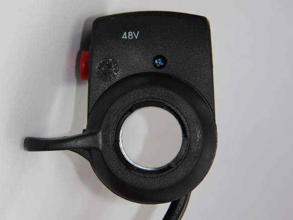

If your throttle does not have the voltage printed on the casing like the ones shown above, it is likely to be a 36V throttle, as the 24V and 48V throttles were typically marked, whereas the 36V throttles were not.

The external controller conversion on the motor itself should be relatively easy on the MP5, as it only requires the three phase wires and the five Hall sensor wires to be extended out of the motor to reach the external controller:

You will find that the motor will be much noisier if you don't use a sine wave controller, and you will obviously lose the Bluetooth functionality that the MP5 controller provides.
Alan 

