Author Topic: Second MP5 vector controller failure  (Read 14450 times)

Offline Andyl33

  • Confirmed
  • New Member
  • *
  • Posts: 13
Second MP5 vector controller failure
« on: June 12, 2018, 05:18:18 PM »
I converted my mountain bike with an MP5 and ten 6S 5Ah lipos at the end of 2015 and is my main method of getting around the city and riding trails in the mountains - was overjoyed with it.
I upgraded the battery pack using harvested laptop 18650s with a configuration of 14S16P, and that also worked well, although regen wouldn't work until the charge level dropped a bit.

First controller failure:
Last November, I rode about 20km to return some dead lead acid UPS batteries, and on the way back about 2km from home, I was waiting at some lights. I went to accelerate and nothing happened. Checked all the cables and connections, as it has been known for the throttle connector to undo.
No visible problems, no bluetooth, no life at all... so I took the controller apart as returning it is really not an option.
I checked everything - the main capacitor was a bit bloated, so suspected that - hunted high and low for a similar spec and found nothing.  80V 1000uF in that size is really non-standard. Voltage ratings normally go in steps from 63V to 100V, and any 100V capacitors would be too big to fit in the small space.
So, I thought I'd try a 63V cap, and bought a couple from my local shop with the intention of using a lower voltage battery.

On further inspection, I noticed a really tiny chip on the backside of the top circuit board with a possible sign of failure on it - using a phone camera I managed to identify the marking on it:
SM5B
After some googling it appears that this is an 80V buck converter which seems logical in spite of its tiny size, but the id ambiguously refers to LM34923MM or LM34923MMX.
These chips have very different specifications and are certainly not interchangeable, so I would like to know which one the MP5 uses, and I suspect many other users would like to know!

That was then... I gave up and ordered another controller that appeared on ebay, it arrived a couple of weeks later in February, installed it and it worked... Happy again!

Until last week... :-(
I was coming down a steep hill, using regen and it was working for a while and then it stopped braking. I continued using manual brakes but the throttle didn't work. Nothing. No bluetooth light either. Checked connections etc...
So, had to ride back home 15km with a 40kg bike which wasn't very enjoyable but I survived :-)

So faced with another dead controller, I took it apart, spent an hour delicately cleaning out the silicone potting compound again, and cannot see any possible cause of failure.
What component would likely fail if the motor was generating a higher than expected voltage?  The 15810 mosfets look fine, and are apparently rated to 100V.
A circuit diagram would help!

I want to identify and fix the problem, and that SM5B chip seems the likely culprit.
Does anyone know which of the two types it is?
I could buy both kinds and try them and it would either work or not, but surely someone at GM could be able to provide some basic info?

Is it also safe to power up the controller without the motor connected? This would help to check voltages and waveforms.

I think I'll explore using an external controller with it, one that can do 80V or more - I think someone on Endless Sphere did this successfully.
I really can't afford to buy and wait for a new controller every month, but neither can I live without my bike.

(Also on both controllers, the battery indicator light on the throttle failed after a couple of weeks, and I suspect the controllers gave up supplying voltage to it - GM should look at this)

Have to say that I'm pretty disappointed now but hope that the designers of the controller can improve them so that they perform reliably.

Offline Bikemad

  • Global Moderator
  • Professor
  • PhD. Magic
  • ******
  • Posts: 5,553
Re: Second MP5 vector controller failure
« Reply #1 on: June 12, 2018, 08:04:04 PM »
Hi Andy andto the forum.

Unfortunately, I have no idea which of the two types of chip is used.  :(

Is it also safe to power up the controller without the motor connected? This would help to check voltages and waveforms.

Over recent years, I have done this countless times using a 0-60V benchtop power supply with different GM controllers and have never experienced any problems.
I also discovered that a mere 12V supply is sufficient to provide adequate power for programming purposes.  ;)

(Also on both controllers, the battery indicator light on the throttle failed after a couple of weeks, and I suspect the controllers gave up supplying voltage to it - GM should look at this)

This sounds a bit strange, as the LED battery gauge in the throttle is not dependant upon the controller.
The battery indicator board inside the throttle unit is fed directly with the full battery voltage "en route" to the controller (there's a direct connection to the main battery positive cable inside the molded junction block where the five cables meet near to the controller) therefore it is not being supplied by the controller.


Therefore the battery LEDs should still light up even with a dead controller (unless the failed controller has caused a direct short circuit between battery + and Battery -) resulting in the battery's BMS shutting off the power.

The basic battery gauges on the throttles were originally intended for use with lead acid batteries, therefore the reduced voltage drop during discharge of a Lithium pack, coupled with a higher than 48V nominal voltage (51.8V for a 14S pack or 51.2V for a 16S LiFePO4 pack) makes these gauges virtually useless as far as indicating the battery's actual capacity is concerned:


I have just tested a 48V twist throttle and here are my results:

All three LEDs remain brightly lit from 60V down to 48.3V:
  • The Green LED turned Off abruptly at 48.2V
  • The Amber LED turned Off abruptly at 42.7V
  • The Red LED faded gradually from ~40V downwards until it was completely Off at 30V
If you put these figures into the above chart, you will see that a 16S LiFePO4 (or 14S lithium battery) would need to be at least 95% discharged before the Green LED would turn Off.
The old style 13S lithium pack would need to be ~93% discharged before the Green LED would turn Off.
With a 48V lead acid battery, the Green light would turn off with 30% capacity still remaining, and the Amber LED would turn Off with ~3% remaining.

The battery gauge on a 24V or 36V throttle will not last long if subjected to a 48V battery, whereas the battery gauge on a 48V throttle should not die, it should simply continue to be totally inaccurate (All 3 LEDs constantly lit up right throughout the majority of the discharge period) with a 14S lithium battery.
However, the accuracy of the 48V gauge can be improved by adding a 500 Ohm variable resistor in series with the battery voltage supply to the gauge's PCB.
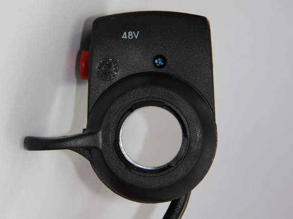


If your throttle does not have the voltage printed on the casing like the ones shown above, it is likely to be a 36V throttle, as the 24V and 48V throttles were typically marked, whereas the 36V throttles were not.  ::)

The external controller conversion on the motor itself should be relatively easy on the MP5, as it only requires the three phase wires and the five Hall sensor wires to be extended out of the motor to reach the external controller:


You will find that the motor will be much noisier if you don't use a sine wave controller, and you will obviously lose the Bluetooth functionality that the MP5 controller provides.

Alan
 
« Last Edit: June 12, 2018, 08:58:21 PM by Bikemad »

Offline Tommycat

  • Confirmed
  • Bachelor of Magic
  • ****
  • Posts: 179
Re: Second MP5 vector controller failure
« Reply #2 on: June 13, 2018, 12:43:42 PM »
I'd be suspicious of an upper wiring harness/component problem taking out the lower harness main power and eventually the 5 volt dc regulated power which I would guess your mystery chip provides.


Have 5 volts at the board? If not perhaps a temporary external supply will help sort things out. AFTER you check for shorts... ;) 


Use these for wiring checks, and voltage check points.


Oh, and make sure you have no loose ends!   :D

Regards,
T.C.


See my completed Magic Pie V5 rear hub E-Bike build  HERE.

Offline Andyl33

  • Confirmed
  • New Member
  • *
  • Posts: 13
Re: Second MP5 vector controller failure
« Reply #3 on: June 15, 2018, 08:48:06 PM »
Unfortunately, I have no idea which of the two types of chip is used.  :(

Thanks for your reply Alan,

I ordered 3 chips from https://www.digikey.at/product-detail/en/texas-instruments/LM34923MM-NOPB/LM34923MM-NOPBCT-ND/3527216 on Wed evening, and they arrived today!
€10 for the chips and €20 for shipping... but much cheaper and quicker than a new controller.
So now I have the delicate task of trying to replace it and hoping it'll work. This thing is *tiny*!
Disconnecting the board and reflowing in the oven would be a hassle, so willl try with a heat gun - unfortunately it doesn't have any thermal control but I could bleed off some of the airflow and direct that more precisely and make a mask with some alu foil to protect other components, or maybe I'm worrying too much!

Image of suspect chip attached, hopefully.

Is it also safe to power up the controller without the motor connected? This would help to check voltages and waveforms.

Over recent years, I have done this countless times using a 0-60V benchtop power supply with different GM controllers and have never experienced any problems.
I also discovered that a mere 12V supply is sufficient to provide adequate power for programming purposes.  ;)

Thanks for that info - that's really encouraging.

(Also on both controllers, the battery indicator light on the throttle failed after a couple of weeks, and I suspect the controllers gave up supplying voltage to it - GM should look at this)

This sounds a bit strange, as the LED battery gauge in the throttle is not dependant upon the controller.
The battery indicator board inside the throttle unit is fed directly with the full battery voltage "en route" to the controller (there's a direct connection to the main battery positive cable inside the molded junction block where the five cables meet near to the controller) therefore it is not being supplied by the controller.

If your throttle does not have the voltage printed on the casing like the ones shown above, it is likely to be a 36V throttle, as the 24V and 48V throttles were typically marked, whereas the 36V throttles were not.  ::)

I remarked on it because the battery indicator leds started working again when I replaced the controller which surprised me - it's not an issue as I don't particularly need them and usually kept it switched off.
The throttle is a different type than the photo, a two tone gray fascia and black body, but does appear scaled for 48V.

The external controller conversion on the motor itself should be relatively easy on the MP5, as it only requires the three phase wires and the five Hall sensor wires to be extended out of the motor to reach the external controller:

You will find that the motor will be much noisier if you don't use a sine wave controller, and you will obviously lose the Bluetooth functionality that the MP5 controller provides.

If I eventually do go down this route then I would definitely go for a sine wave controller with higher voltage and replace the thin power cable with something much more appropriate. I love the quietness and lack of cogging, and also have 800 18650 cells looking for something to do :-)
I'm sure there are other controllers with bluetooth, but it isn't essential - the BMS I have has bluetooth so it gives me the state of all cells as well as total voltage, current and remaining capacity, a history log for each cell, ability to set thresholds and even a lock to disable output which is useful to save sparking on the main connector.
DIY Tech & Repairs on youtube did a useful review of it, and I bought a 60A version based on that.
https://youtu.be/sGj9UrfEcAw
Bluetooth on my Samsung S3 is a bit temperamental, but it seems to work OK.

Offline Andyl33

  • Confirmed
  • New Member
  • *
  • Posts: 13
Re: Second MP5 vector controller failure
« Reply #4 on: June 15, 2018, 11:37:50 PM »
I'd be suspicious of an upper wiring harness/component problem taking out the lower harness main power and eventually the 5 volt dc regulated power which I would guess your mystery chip provides.

Have 5 volts at the board? If not perhaps a temporary external supply will help sort things out. AFTER you check for shorts... ;) 

Use these for wiring checks, and voltage check points.
Oh, and make sure you have no loose ends!   :D

Regards,
T.C.

Thanks for the tips TC!

My controller has a different layout from the one shown - here are all my layers attached... I did make a list once of what colour wires went to which pins but I've mislaid it and may have to do it again.

I think I need to check the 78M05 too, probably best to desolder it and make up a test rig for it before attempting to change the LM34923 and possibly damaging it too.

If it does all work again, I'll need to find some similar silicone potting compound before it rains!

Offline Andyl33

  • Confirmed
  • New Member
  • *
  • Posts: 13
Re: Second MP5 vector controller failure
« Reply #5 on: June 15, 2018, 11:39:26 PM »
And one more showing the wire colors for reference...

Offline Tommycat

  • Confirmed
  • Bachelor of Magic
  • ****
  • Posts: 179
Re: Second MP5 vector controller failure
« Reply #6 on: June 16, 2018, 09:36:49 PM »
Hi Andy,
Thanks a lot for the terrific pictures! Yeah, that pic is from an older Pie 4 I believe. But good to note that the wiring color/terminations are the same. May I use your pictures for some updated illustrations?


Wires to pins? Stock MP5 Pic...


So the 78M05 is probably the 5 volt output? Had you lost the 5 volts on both boards?

And who rides in the RAIN anyway?  :P
See my completed Magic Pie V5 rear hub E-Bike build  HERE.

Offline Andyl33

  • Confirmed
  • New Member
  • *
  • Posts: 13
Re: Second MP5 vector controller failure
« Reply #7 on: June 17, 2018, 01:53:16 AM »
Hi Andy,
Thanks a lot for the terrific pictures! Yeah, that pic is from an older Pie 4 I believe. But good to note that the wiring color/terminations are the same. May I use your pictures for some updated illustrations?
Of course!

So the 78M05 is probably the 5 volt output? Had you lost the 5 volts on both boards?
Only tested the one on my 2nd board - I desoldered it, put it across a 3S lipo and got 5V out, so it's good.

I removed the LM34923 chip eventually - it did not come off easily so I used more heat than I think was appropriate and it still didn't budge so I think it was glued as well!
Had to be careful not to nudge any of the other SMD components as they were totally floating... would have been a really really bad time to sneeze!
I eventually used a blade to cut the legs and pick them out with a soldering iron without lifting any tracks.

During this I also partially melted the wire loom, so will replace it with the one from the previous controller.
(This is OK - the cable sheath was damaged anyway when the wheel tore itself out of the drop outs on my previous frame through not using torque arms! Since rectified.

It's really not easy using a Black & Decker heat gun on this without setting fire to and/or melting everything else on the desk, including bits of me that might get in the way.
Now working up the motivation and courage to replace the loom and the chip, check shorts and then power up!

And who rides in the RAIN anyway?  :P
I do... (or did!).
In Hungary it isn't just the rain - some roads are so bad that pools of water form in sun-melted grooves which spew tsunamis when a truck goes through them. This is not much fun when it happens, as a solid wall of water exerts quite a force, so it helps to be prepared with full waterproofing, and insulation when it's -25 °C in winter.
As they apparently say in Iceland: There's no such thing as bad weather, just inappropriate clothing!

Offline Tommycat

  • Confirmed
  • Bachelor of Magic
  • ****
  • Posts: 179
Re: Second MP5 vector controller failure
« Reply #8 on: June 18, 2018, 02:01:56 PM »
Only tested the one on my 2nd board - I desoldered it, put it across a 3S lipo and got 5V out, so it's good.

I removed the LM34923 chip eventually - it did not come off easily so I used more heat than I think was appropriate and it still didn't budge so I think it was glued as well!
Had to be careful not to nudge any of the other SMD components as they were totally floating... would have been a really really bad time to sneeze!
I eventually used a blade to cut the legs and pick them out with a soldering iron without lifting any tracks.

During this I also partially melted the wire loom, so will replace it with the one from the previous controller.
(This is OK - the cable sheath was damaged anyway when the wheel tore itself out of the drop outs on my previous frame through not using torque arms! Since rectified.

It's really not easy using a Black & Decker heat gun on this without setting fire to and/or melting everything else on the desk, including bits of me that might get in the way.
Now working up the motivation and courage to replace the loom and the chip, check shorts and then power up!


All above my paygrade... :o


Is this the way you see it up close and personal?


Edit: Back from the future. Replaced picture with latest and greatest.   ;)


errrrr is speed the same as the pedelec input?
« Last Edit: June 20, 2018, 12:36:15 PM by Tommycat »
See my completed Magic Pie V5 rear hub E-Bike build  HERE.

Offline Bikemad

  • Global Moderator
  • Professor
  • PhD. Magic
  • ******
  • Posts: 5,553
Re: Second MP5 vector controller failure
« Reply #9 on: June 18, 2018, 04:05:49 PM »
errrrr is speed the same as the pedelec input?

No, SP is the throttle signal input, the yellow wire is for the pedelec input.

I think you need to correct two entries as shown here:
Green = THROTTLE   SP
Yellow = PAS or PEDELEC TA

(It's actually TA printed on the circuit board not TH, see picture below)

You could even correct the word "Receive" while you are in "edit mode" if you wanted to.
(i before e except after c)


Alan


Offline Tommycat

  • Confirmed
  • Bachelor of Magic
  • ****
  • Posts: 179
Re: Second MP5 vector controller failure
« Reply #10 on: June 19, 2018, 11:56:45 AM »
Thank you Alan! Good catches. Will correct. I like the way you can see the labeling in your photo...may I incorporate it? Sorry for the drift Andy. Will start-up a controller input discussion in another thread.  ;)
See my completed Magic Pie V5 rear hub E-Bike build  HERE.

Offline Bikemad

  • Global Moderator
  • Professor
  • PhD. Magic
  • ******
  • Posts: 5,553
Re: Second MP5 vector controller failure
« Reply #11 on: June 19, 2018, 09:43:16 PM »
The photo was not taken by me, I'm pretty sure it was cropped from a larger photo in a previous post by another member of this forum, but I can't remember who.    :-[

I'm sure the original poster wouldn't object to it being used for the benefit of others.  ;)

Alan


Offline Andyl33

  • Confirmed
  • New Member
  • *
  • Posts: 13
Re: Second MP5 vector controller failure
« Reply #12 on: June 21, 2018, 05:22:45 PM »
Happy news - finally got motivation together to solder in the new chip and replace the wire loom from the previous controller.

Was not easy aligning by hand something to about 50 micron accuracy while trying to keep it still, dodging the heat gun blast, trying not to overheat it and not disturbing the other components whose solder was also molten.
I had 3 pairs of reading glasses on to be able to resolve the detail, and it looked OK afterwards.

Finally put it all back together again, mounted the wheel, plugged in the control harness and powered up. No bang!
Twitched the throttle and she spun! Yayyyy! So happy!

Now just have to replace a spoke before pumping up and I'll be mobile again and able to give it a more thorough test.
At least if it happens again I have another 2 spare chips, but the thought of going through this again doesn't fill me with joy.

Will report back after a couple of runs.

Cheers,
Andy

Offline Tommycat

  • Confirmed
  • Bachelor of Magic
  • ****
  • Posts: 179
Re: Second MP5 vector controller failure
« Reply #13 on: June 22, 2018, 02:51:39 PM »
Outstanding work on the board! ;D My concern would be that you did not find the root cause of the issue, just fixed the results of...did you check things out, harness, wiring, components, regulated voltage amperage draw? After all that hard work I would sure look it over closely. ;)
See my completed Magic Pie V5 rear hub E-Bike build  HERE.

Offline Andyl33

  • Confirmed
  • New Member
  • *
  • Posts: 13
Re: Second MP5 vector controller failure
« Reply #14 on: June 22, 2018, 03:08:30 PM »
I'm pretty sure the root cause was sustained regen voltage overload by failing while coming down a very steep hill with a 14S battery, 40kg bike and 75kg passenger. It never failed before on similar situations, but it gave up on this one. I had no reason to suspect the cables.
By the look of the chip it had swelled slightly, so it wasn't man enough for the job - hopefully the new chip will fare better.
At least I know the cause, and that the replacement part I shared above works for anyone else that may come across the same problem.
Apparently the controller is notorious for failing, and this is probably the reason why - I hope GM can fix it in a newer version.

So, I got the wheel on, spokes fixed (I really need a complete set of new ones as all the GM spokes failed at the bend, and a rim!)
Pumped it up and the tyre went flat after a couple of hours, so am currently about to fix that...
My woes aren't totally over yet, it never seems to end!