Hi Jay,
Unfortunately I have never opened up the wiring on either the plug or the socket on that connection so I have no idea whether the colours are a direct match or not.
You will only need to have 6 wires from each cable connected to the other cable as there is one unused wire and the program signal/reverse wire is not used in the control harness.
The original MPIIIs had 8 pin connectors, but I think the later ones may have been 10 pin connectors.
The wiring for the earlier MPIII can be seen
here but it does not show what colour wires are used inside the main harness.
It is possible to damage the controller if the battery was connected with the wrong wires connected together
(or simply touching against each other when the connector plug/socket was broken).
It should be possible to identify the function of the wires on the motor harness by removing the controller and using an ohmmeter to check for continuity to locate where each wire is connected inside the controller.
The connections to the controller are not shown on the diagram but there are two thicker battery cables
(Red and Black) and six smaller wires:
- Thick Red - Battery +ve
- Thick Black - Battery -ve
- Thin Green - Throttle signal
- Thin Blue - Brake signal
- Thin White - +5V supply from controller provides power to Throttle and Pedelec hall sensors (also receives power from USB programming cable)
- Thin Red - Cruise signal
- Thin Black - Reverse & Program Rx - This wire was only used for programming via the broken plug and does not need to connect to the control harness.
Yellow - Pedelec signal Ignore this wire as it does not go to the broken connector
Once you have made a note of the function and colour of the seven wires
(and the colour of the one unused wire) you can then refit the controller back into the motor.
Now the control harness wires need to be identified using the same continuity check method:
Connect the black lighting ground wire to one of your meter leads and then check each of the loose wires in turn until you find continuity and then make a note of the colour of the wire.
Once you have found the Battery -
(ground) wire you can use the brake lever to see which other loose wire is switched to ground when the lever is pulled to locate the brake signal wire
(note the colour of the wire again).
And you can use the cruise button to see which other wire connects to ground when the cruise button is pressed
(note the colour of the wire again).
Connect the red lighting feed wire to one of your meter leads and press the red button on the throttle and check each of the loose wires in turn until you find continuity and then make a note of the colour of the "Battery +" wire.
You should now be left with 4 unidentified wires, and two of them will not need to be connected. You just need to identify the throttle signal wire and the +5V wire.
Connect you meter lead to each one of the unidentified loose wires in turn and use a small sewing needle held against the other meter lead probe to gently touch into the +5V or the Throttle Signal contact on the multi-block connector
(refer to the diagram in the above link) if neither have continuity, swap the meter lead to the next loose wire and try again.
Repeat this for the other two wires until you identify the throttle signal, +5V and the two unused wires.
Refer to your notes and see if the colours are the same for the different functions on both harnesses.
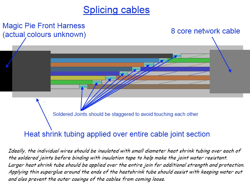
If they are the same, simply solder up the matching six wires and ensure that they are well insulated along with the two remaining unused wires on each cable.
I would stagger the joints if possible as shown here:
You should now be good to connect the battery and check if it still works.

Please let us know the results of your checks, and whether the controller survived.
 Alan
Alan 

