Author Topic: Connecting 2 BAC282P controllers to a common set of controls  (Read 6124 times)

Offline JDMarshall

  • Confirmed
  • New Member
  • *
  • Posts: 1
Connecting 2 BAC282P controllers to a common set of controls
« on: September 26, 2012, 02:01:26 AM »
I am trying to install 2 MPII wheels on a vehicle with one set of controls.  What is the best way to wire them togrther?  I am also using an Model: FSC-010 -- Foot Throttle.  What are the wiring connections for that?

Jan Marshall
Nampa, Idaho, USA

Offline truly_bent

  • Confirmed
  • Bachelor of Magic
  • ****
  • Posts: 159
Re: Connecting 2 BAC282P controllers to a common set of controls
« Reply #1 on: September 26, 2012, 11:33:32 AM »
Are they running off the same battery pack? That's to say, do the controllers share the same common potential? Are the two battery negatives (-) connected?

If so, i'd be tempted to run the output from the throttle into both controllers and not expect to let any smoke outta the wires (buy an extra throttle before trying this at home kids). That holds true for any other controls split between the two controllers as well.

If not, I wouldn't chance it - unless The Perfessor says otherwise.

Jeff

P.S. Another option is to opto-isolate all the shared signals to one of the controllers, but that gets expensive, especially with analog (throttle).
Burley Canto recumbent w/ MP II, Lyen 18FET controller, 48V 20AH LiFeP04, Cycle Analyst, and 4 pounds of zip-ties

Offline Bikemad

  • Global Moderator
  • Professor
  • PhD. Magic
  • ******
  • Posts: 5,523
Re: Connecting 2 BAC282P controllers to a common set of controls
« Reply #2 on: September 26, 2012, 03:45:19 PM »
Hi Jan andto the forum.

If they are running off a single battery, it must be capable of delivering at least 60 Amps or you will need to limit the current settings on each controller so as not to exceed the battery's maximum and continuous power output.

A single throttle should be fine, but I haven't seen any connection details for the foot throttle so I don't know whether it has a switch output wire as well as the throttle signal.

If you can post some details of the connector/s including the colour and number of wires etc., then hopefully we should be able to determine which wires need to go where.

The typical hand throttles use only three wires for throttle control:
Red = +5V (Throttle Power supply)
Black = 0V (Ground)
White (or sometimes Green) = Throttle output signal
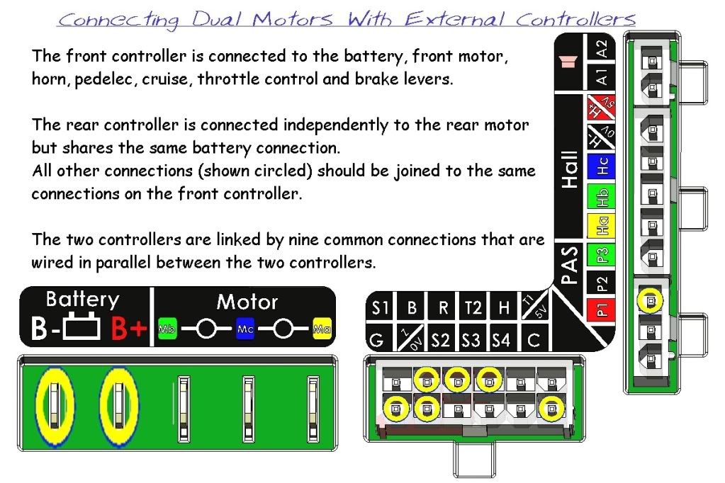
 (~1-4.5V)

Both controllers will need to share a common negative ground connection, and the following wires can then simply be connected in parallel between the two controllers:
  • Throttle Signal (T2)
  • Brake Signal (B)
  • Reverse (R)
  • Cruise (C)
  • Ground Z/0V
It has been previously suggested that it's not a good idea to join the +5V outputs between the controllers (T1/5V and P1) as this can supposedly cause problems with the two 5V regulators as each one tries to regulate the joined 5V output.

This diagram should help:


Alan
 
« Last Edit: July 02, 2017, 03:08:06 PM by Bikemad »