Author Topic: circuit diagram  (Read 11222 times)

Offline mickyb

  • New Member
  • *
  • Posts: 9
circuit diagram
« on: May 01, 2011, 08:24:42 PM »
I need an equivalent circuit diagram of the motor (48V,1000W). We are making an analysis of the motor for a final project for college.

Offline Bikemad

  • Global Moderator
  • Professor
  • PhD. Magic
  • ******
  • Posts: 5,523
Re: HBS Circuit diagram
« Reply #1 on: May 01, 2011, 09:18:22 PM »
Mike, the wiring diagram for the HSB motor is pretty straightforward as it consists of five small wires for the hall sensors, and three thick phase wires as shown here:


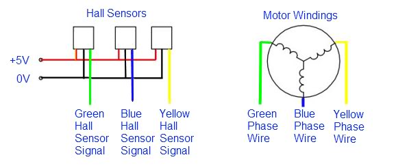
The HBS motor is wired in a Star configuration as shown above (also referred to as Wye or "Y"), but each of the three phase wires are actually made up of 17 separate coil groups connected in series.

You motor should have a total of 46 Magnets (Poles) and 51 Slots (Coils).

Hope this helps.

Alan
 
« Last Edit: June 30, 2017, 10:23:02 PM by Bikemad »

Offline mickyb

  • New Member
  • *
  • Posts: 9
Re: circuit diagram
« Reply #2 on: May 01, 2011, 09:35:51 PM »
Alan, do you know what size (ohms) are the resistors??

Offline Bikemad

  • Global Moderator
  • Professor
  • PhD. Magic
  • ******
  • Posts: 5,523
Re: circuit diagram
« Reply #3 on: May 01, 2011, 09:42:34 PM »
Those are not separate resistors, they are the coil windings and I would expect to measure around 0.6 Ohm between each pair of phase wires.

Your stator should look similar to this:


Alan
 
« Last Edit: May 01, 2011, 09:45:12 PM by Bikemad »

Offline mickyb

  • New Member
  • *
  • Posts: 9
Re: circuit diagram
« Reply #4 on: May 01, 2011, 10:21:14 PM »
Alan, so this is an AC motor because of the wye configuration??

Offline Bikemad

  • Global Moderator
  • Professor
  • PhD. Magic
  • ******
  • Posts: 5,523
Re: circuit diagram
« Reply #5 on: May 01, 2011, 10:54:08 PM »
Alan, so this is an AC motor because of the wye configuration??

It's called a Brushless DC motor because it has no brushes, and it is powered from a DC supply (the battery).  The speed controller is basically an electronic version of the commutator and brushes found on a conventional brushed motor. I try to visualise it as being more like a three pole brushed motor, as the current is continually being switched between the three phases ;)

Alan