Jerry,
The last two drawings appear to be wired the same, but unfortunately none of your three drawings will work correctly.

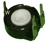
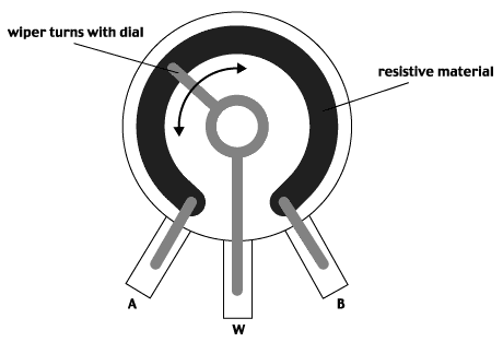
The preset has three contacts, all of which need to be used for it to work correctly:


Pin
A connects to ground, via a switch if used
(Black wire on the throttle connection)Pin
B connected to the throttle signal wire
(White wire coming from the twistgrip or thumb throttle)Pin
W connects to the throttle signal connection on the controller
(White wire on the black 3pin connector on the Magic Pie wiring harness)This potentiometer
(variable resistor) is being used as a simple voltage reducer.
With the dial turned fully towards Pin
A 0% of the signal voltage will be sent to the controller.
With the dial turned fully towards Pin
B 100% of the signal voltage will be sent to the controller.
Here's a quick example:
If the throttle device is held the fast position
(100%) signal voltage is sent out from it.
If the dial is pre-set in the middle position, only 50% of the throttle signal voltage will be forwarded to the controller.
Therefore half throttle is the maximum that would be available to use.
When the switch
(if fitted) is turned off, the pre-set restrictor will no longer have any effect on the throttle, which will continue to operate just as normal.

Hopefully this should make sense to you now, so long as I haven't confused you too much.
 Alan
Alan