G'day Leslie,
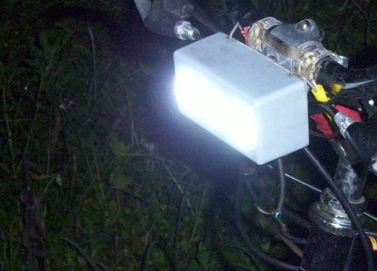
I would be interested in building this kit of yours for myself to be run off anywhere from 24v to 60v. I'm considering putting one of a pair of LED car driving lights onto my bike for its brightness and look. See attached picture. Could you give a list of components needed and how to build and tune it.
Muzza
Yeah sure.
LM2576HV 5 pin simple switcher IC.
Data sheet<<<<
I got 10 of them here for about $16
http://cgi.ebay.com.au/10-pcs-Switching-Regulator-LM2576HVT-ADJ-LM2576-TO-220_W0QQitemZ160390583126QQcmdZViewItemQQptZLH_DefaultDomain_0?hash=item2558061356Make sure you gets the HV and they are good to up to a nice 3 amps. You could run a set of 3v crees on one without going series..
Thats 60v to 3v with 75% efficiency. 9 watts.
At 12v you could pull 36 watts out of her.

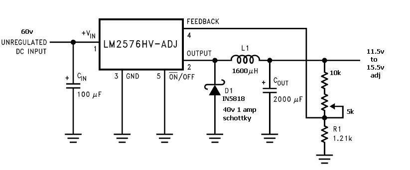
There are 5 pins to the switcher.
1: Input
2: output.
3: ground
4: feedback regulation
5: ground and or standby switch.
This diagram I altered should get you an adjustable DC to DC conveter from 11.5v to 16.5v.
Best at 12.6v 600ma for max efficiency.
If you want more current take the inductance down and use a beefier schotkky diode.

The feedback works on a voltage divider from R1 and the 10k base resistor and series trim fro adjustable voltages. You could use a 50k variable resistor and make the output voltage swing all the way.
For around 12v use a 1.2k resistor for R1 it doesnt matter much about the output.
The 10k resistor is there so you don't blow that sh!t up and with the 10 turn 5k VR adjustable should be a smoother adjustment of the output.
Stick to the above circuit and she should be dandy.
And the 5k Variable resistor is for adjustable voltage. 10 turn variable resistor pots are the way to go.
Feedback voltage = 1.23v
The equation is for 12.6v
R2=1.2k(12.6v/1.23) - 1.2k
R2 =11k
R2 = the 10k and variable resistor in my circuit above.
The input filter cap I used a 63v 100uh
The output filter cap I used a 25v 2000uh to save space, but when practising use a 63v cap so you don't have any accidents or of cause desire voltages higher than 25v.
The schottky diode I used is from Jaycar. IN5818 40v 1 amp. Its good for up to 37v output @ 800ma.
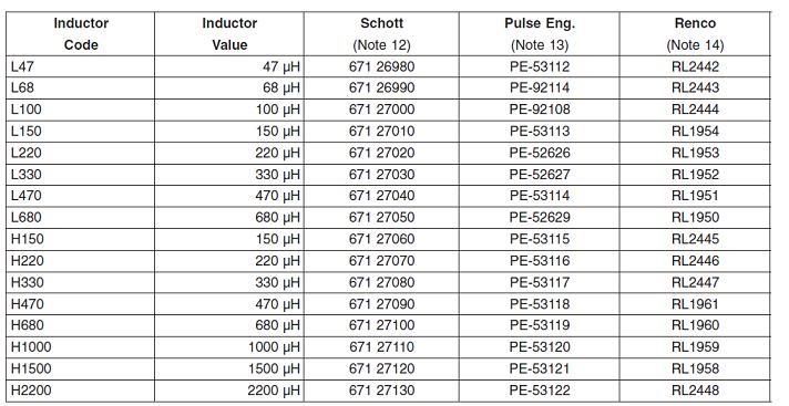
The inductor by the data sheet has a chart.

Use the equation (Vin-vout)*vout/vin*1000/switch frequency 52khz
Say
52v input - 12.6v output = 39.4
39.4(12.6v/52v) = 9.54
9.54(1000/52khz) = 183.
The figure 183 is used on the vertical axis on the chart above and go along the bottom and choose desired amperage.
I came up with a H1500 for 600ma in between 700ma and 500ma output and improvised it to 1600uh by looking where my 183 figure ran up to.
For a 9 watt cree lamp like the one in you picture, use a 1000uh inductor rated at 1 amp. A 950uh if you want to do a rear light as well.
Choose an inductor suitable for 52khz switching. I bought a yellow one from Jaycar. Both L and H inductors are uh however they size differs.

 http://www.thierry-lequeu.fr/data/PC500_51.pdf
I used the above site to gather the dimensions.
My inductor is
27mm outside diameter
15mm inside diameter
11mm high
You want the same size. I bought mine from jay car and rewound it to suit. You should be able to wind your toroid with .5mm enamel wire and just squeeze it in a single layer for best results. ermm maybe a quick 2nd layer around the toroid..
God knows how many turns I put on it but if you get this far I can work it out for you. I just used an inductance meter and kept winding intil I got over 1500uh.
I used 3 layers.
Its still going very well and Ive used 3 auto leds on the front now and one on the rear.


Honestly it took me some time to be able to build these DC to DC converters in an afternoon. Sourcing parts and stuff. I do have spare toroids and ICS to boot. And the multimeter that measures inductance I bought from Jcar takes all the guess work out of the winding of the toroids.
I love learning and doing this stuff but it would be easier to buy one. But heck I would learn jack doing that.