Hi and

to the forum.
Unfortunately there is no set colour association with the functions of the harness as the colours seem to vary between harnesses.
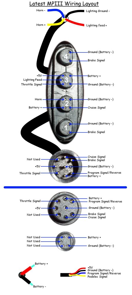
Here is the wiring diagram for the early MPIII which shows the pin allocation but not the wire colours:

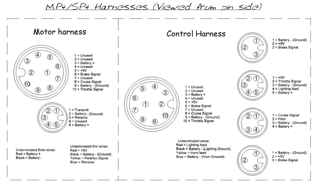
As your connector seems to have 9 wires coming from it, I assume yours has the later 10 pin harness as used on the MP4 and MP5 control harness.
The following diagram shows the pin allocation on the 10 pin connector:

You will need to check for continuity between each pin and each of the coloured wires coming from the connector to determine the function of each of the coloured wires before you can connect them to your replacement controls.
The following diagram shows the wiring connections for the original Magic Pie, which might be useful as it shows the various common ground connections from each of the controls:

Click image to view full size.
The brakes, cruise and horn switches only require two wires each and the polarity of each pair does not matter.
You can use a continuity tester or ohmmeter to determine which pairs of wires are connected when each of the switches is operated if they are not already identified.
To determine the function of each of the wires coming from the thumb throttle, you may need to
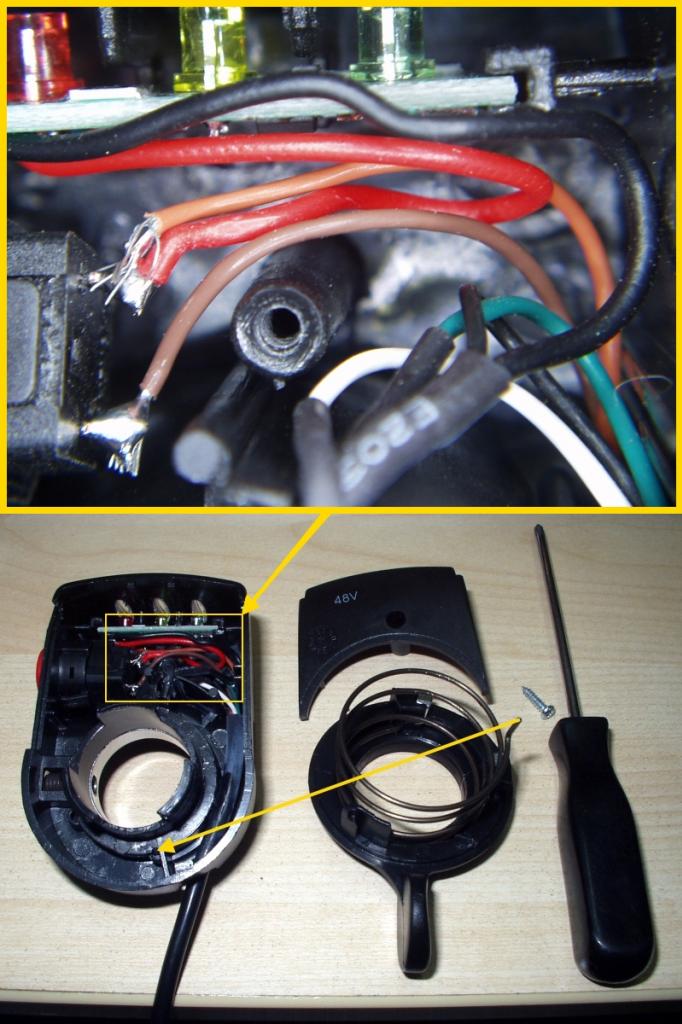
open up the throttle unit. I realise your thumb throttle is different to the one shown in the link, but I'm guessing that it will probably come apart in a similar fashion and allow you to take a good look at the wire colours and their associated connections inside.
In the following picture the Hall sensor wires are as follows:
- White = +5V
- Black = Ground (0V)
- Green = Signal output (0.8-4.5V)

Hopefully this information will help with your repair, but if you need further assistance please provide further information with pictures if needed.
Alan