Hi Madman and

to the forum.
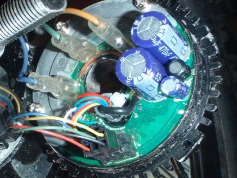
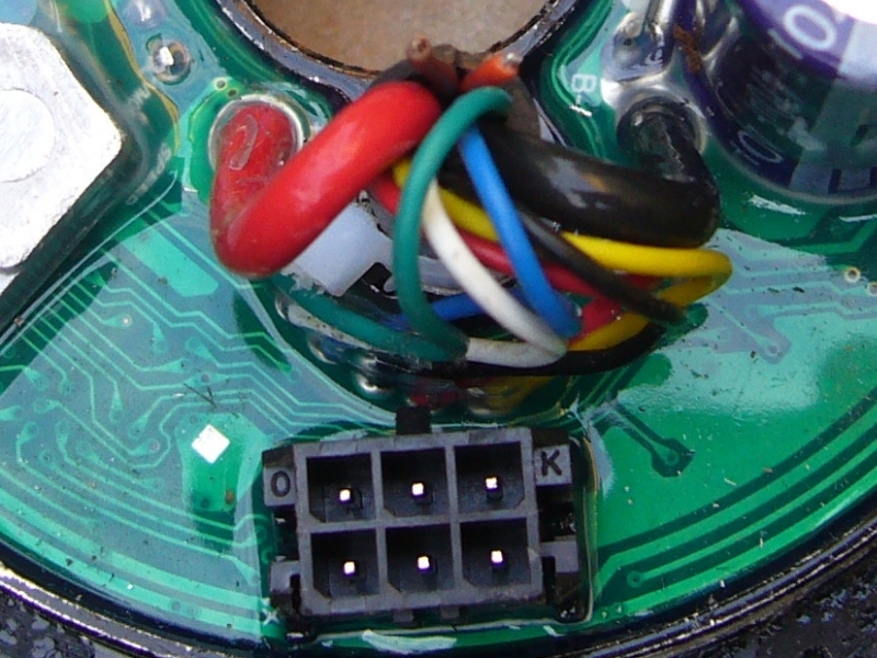
I have carried out a quick search of the forum, but the only pictures I can find showing the wiring connections on the universal controller are these:


Unfortunately, the camera angle does not make it very easy to determine the exact wire locations on the controller's
PCB.
I don't have one of these controllers, so I am unable to look at one to obtain the information that you require, but
Gary (GM Canada) may have one of these in stock that he can hopefully take a close look at to obtain the correct order of the wire connections/colours etc.
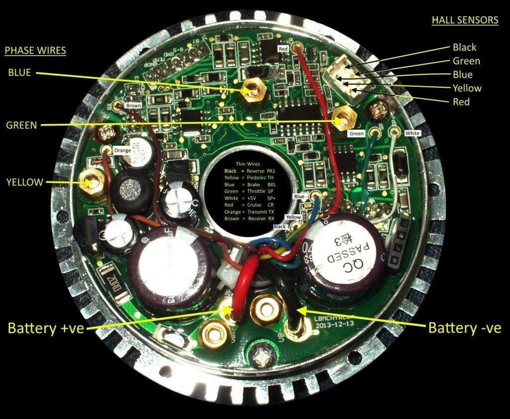
If the coloured wires have the same function as on the sine wave controller, the Orange is for the Data Transmit and the Brown is for the Data Receive:

It is difficult to tell from the pictures whether the wires are simply soldered to the top surface of the PCB, or whether they are "through holes" going to the rear surface of the PCB. But if the wires are only soldered to the copper surface/track of the PCB, then it is possible that the copper surface may have been peeled away from the surface of the circuit board, which might explain why the "2 empty spots" look so clean.
If this is the case, you probably won't be able to resolder those two wires to the circuit board unless you are extremely lucky.

Hopefully
(assuming those two wires are only used for programming) you should still be able to use the controller with its currently programmed parameters if nothing else on the controller has been damaged when the wires were originally pinched.

Please let us know the outcome of this repair.
Alan