Author Topic: Smart Pie 3 Internal Controller Replacement  (Read 5367 times)

Offline Jmant

  • Confirmed
  • New Member
  • *
  • Posts: 4
Smart Pie 3 Internal Controller Replacement
« on: July 31, 2015, 01:28:02 PM »
I am in a world of pain, someone please help!

I have been using my Smart Pie 3 with 8ah water bottle battery nearly every day for about 1.5 years now and have been very happy so far with no troubles (apart from battery longevity greatly diminish over time). Bike was running perfect one day and returned to charge as per normal overnight. Next day unplugged from charge and went to use as normal however there was no power to the motor. There was however lights at my thumb controller to indicate battery level full. I went riding for a while under pedal power to see if the motor would 'kick in' by chance however this did not happen and instead I noticed that the regenerate braking seemed to intermittently ( a couple of times) make it harder to pedal for a while. Back home still no power to motor. Plugged bike in to charge overnight and next day noticed the charger light did not go to green i.e. was still red ' charging' mode when it should have been green 'charged' by the morning.

Did some research next day and decided that I may need a new internal controller. Fortunately for me (well unfortunately really when you read ahead) my wife also has identical Smart Pie 3 on her bike so I decided to swap the internal controller between bikes to be sure that it was the part that was broken and need replacing. I put the good working controller from my wives bike into my dead motor and when I switched the battery on a nasty pop, hiss smoke burn wire episode erupted from (i think) up near the wire plugs where brake and throttle wires connect and I immediately turned the battery off again.

Then decided to put the known faulty internal controller from my bike into wifes good motor and as expected this did not work on her bike (I think this confirms that my controller was the original problem). However did notice that the throttle lights came on and off a couple of times when switching the battery on and off however after a few times switching battery on and off the throttle lights stopped working. At no time did the motor work (as I expected from the suspect broken internal controller).

So I then returned the good previously working internal controller back into my wifes bike to return her unit back into normal operation however her bike now also does not work as I suspect I fried her internal controller when I plugged it into my bike to test..... turned out to be a bad idea....... I now have suspected 2 broken internal controllers.

What could be causing the damage to the internal controllers. Obviously something to do with my bike battery or wiring???? Note I made 100% sure I connected the 3 phase wires and block connector correctly when swapping the controllers (I took photos before pulling the wires off).

I have ordered one new controller from canada to put back into my wives bike (hopefully it works again) but worried that if I put a new controller into my bike I will just fry that again too???????

Advice anyone?

Offline Bikemad

  • Global Moderator
  • Professor
  • PhD. Magic
  • ******
  • Posts: 5,523
Re: Smart Pie 3 Internal Controller Replacement
« Reply #1 on: July 31, 2015, 02:33:04 PM »
Hi Jmant,

I don't know whether the charger input goes through the fuse or not but if the fuse has blown it might prevent the battery from charging.
I suggest that you check the fuses and the voltage output on both bikes to see whether either (or both) of the fuses have blown.

Your bike sounds like it may now have damage to the front control harness or one of the control's connecting cables (brakes, throttle or the cruise/horn unit) but it could be difficult to try and locate the exact fault.
The throttle unit/cable is probably the most likely of the four controls because it contains both battery + and Battery - wires, just like the motor and control harness.

Unfortunately it is impossible to say why the controllers might have failed, assuming this is what has actually happened, but I think a wiring fault allowing Battery + to short across to the +5V circuit could damage the +5V regulator in the controller and without the +5V supply the motor will not run.

Were both Smart Pie kits purchased together or is it possible that one could be a newer version than the other?
I am wondering whether the harnesses may have been wired slightly different making the older motor harness incompatible with the newer control harness connections (and Vice Versa).

Do they both have the same 10 pin connectors between the motor harness and the control harness?

Is there any chance that you may have connected your battery wires to your wife's controller the wrong way around?

I don't know what else to suggest that might help, but please let us know what you find on the fuses.

Alan


Offline Jmant

  • Confirmed
  • New Member
  • *
  • Posts: 4
Re: Smart Pie 3 Internal Controller Replacement
« Reply #2 on: August 01, 2015, 04:55:04 AM »
Hi Alan, thanks for your initial reply.

The battery fuses are okay and output from my and my wifes batteries is 41.8V and 41.5V respectively (fully charged). Voltage output was tested at the connection pins fixed to the bottom of the water bottle batteries (from 2 of 4 pins).

Both Smart Pie kits were purchased within an month of each other and the wiring looks identical to me.  They both have the same 8 (not 10) pin connectors between the motor harness and the control harness. It was an easy swap for the known good controller into my bike for the test. i.e. connect controller to motor, connect battery plug to battery and connect motor harness to control harness. As soon as I turned the battery on to test is when the sound and smoke came from around the front control harness. 

I am confident the battery wires were connected correct way round during the controller swap test (same plug for both bikes). 

My plan from here is to fit the new controller (when it arrives) into my wifes bike and hoping this should get her on the road again. As for my bike, I am reluctant to put a new controller in as is likely it will fry just like it did in the recent test with my wifes controller. Any further advice will be greatly appreciated.

Regards

Jason

Offline Bikemad

  • Global Moderator
  • Professor
  • PhD. Magic
  • ******
  • Posts: 5,523
Re: Smart Pie 3 Internal Controller Replacement
« Reply #3 on: August 01, 2015, 11:10:53 AM »
Hi Jason,

If you only have the 8 Pin connector you must have the original version of the Smart Pie harness which should be the same as the MPIII Layout shown here:


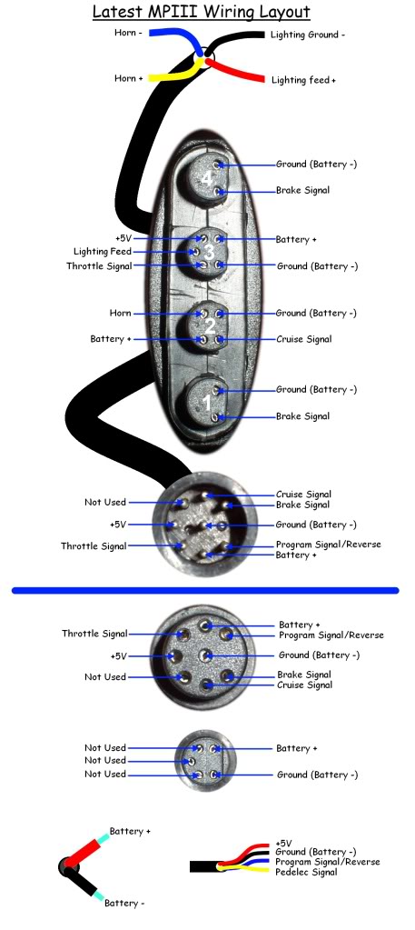
The most obvious way for a short circuit to occur would be if the lighting wires (shown at the top of the diagram) are touching and the red switch on the throttle was turned on.

I suggest you carefully inspect the light and horn wires to see if there are any signs of them touching each other.
Also check the wires for the pedelec and reverse on the motor harness for the same problem.

If you have a multimeter with a continuity setting that beeps to show continuity (or you can simply use the Ohm setting instead) you can use it to check for a short circuit on the front harness.

If you are using the Ohm setting you should set it to a low scale (e.g. 0-200 Ohms) which should then show ~0 on the display when the probes are touched together indicating continuity, and most meters will display a "1" on the left of the display when the circuit is open to indicate there is no continuity.
Make note of the reading obtained when you touch the probes directly together so you know what a direct short should look like. This reading can be as high as 2.5~3.0 Ohm instead of zero on cheap meters using thin test leads and even higher if the battery in the meter is low.

Anyway, you will need to carefully check between all of the pin combinations on the 8 pins in the harness connector.
Start by placing the black probe on the first pin and then touch the red probe against each of the other 7 pins in turn to see if there is a reaction on the meter, being careful not to cause false readings by accidentally touching the two probes together.
Then move your black probe to the second pin and repeat the above test. Repeat this process until all combinations of pins has been tested and make a careful note of which pairs of the connector have continuity (and also record the resistance reading if using an Ohmmeter).

If you are using an Ohmmeter, you may see strange readings between different combinations of the battery+, battery-, throttle signal and +5V, but these should disappear with the throttle unit disconnected.

I suggest you carry out this test with all the controls connected and the red switch pressed in on the throttle.
If you find a short, it would be worth carrying out the test again with the controls disconnected to see if the short disappears, which would indicate whether the short is in the harness or one of the control units (brakes, throttle or the cruise/horn).

Please let us know the results of your testing.

Alan
 
« Last Edit: July 02, 2017, 11:38:28 PM by Bikemad »

Offline Jmant

  • Confirmed
  • New Member
  • *
  • Posts: 4
Re: Smart Pie 3 Internal Controller Replacement
« Reply #4 on: August 02, 2015, 10:15:33 AM »
Hi Alan,
The red switch on the throttle was definitely on and the lighting wires at front harness may have been touching (but not certain). The lighting wires at front harness look burnt ends and this is where the smoke came from when turning the battery on momentarily during the test (and subsequent failure) of the second internal controller fitted from my wives bike. The horn wires at front harness seem okay and are not touching. The wires for pedelec, reverse, ground and +5V on the motor harness all look okay and are not touching.

When using Ohm setting a "1" was displayed to indicate no continuity and when the probes were touched together the reading was "0.8" to indicate a direct short.

When all controls connected with red switch pressed in on the throttle, I got a reading for continuity between:
ground - battery positive
ground - throttle
ground +5v
battery positive - throttle
battery positive - +5v
throttle - +5v

when all controls were disconnected I got a reading for continuity between:
ground - throttle
ground - +5v
throttle - +5v

therefore continuity readings that remained after the controls were disconnected were :
ground and battery positive
battery positive and throttle
battery positive and +5v

The resistance readings during tests were between 3.3 and 6.1

Does any of this make sense to you? What does this mean?

Kind regards

Jason.

Offline Bikemad

  • Global Moderator
  • Professor
  • PhD. Magic
  • ******
  • Posts: 5,523
Re: Smart Pie 3 Internal Controller Replacement
« Reply #5 on: August 02, 2015, 11:06:45 AM »
Hi Jason,

It's not looking good for the control harness as the reading indicate that the copper wires are actually touching each other somewhere inside the harness. :(

If the lighting/horn wires were shorted and the switch turned on, the thin wires involved in the short circuit will have heated up so hot that they will have melted through their insulation. :o
Unfortunately, the red hot ground wire (Battery -) appears to have also melted through the insulation on the throttle signal and the +5V supply wires allowing their copper cores to touch, thus causing the shorts in the harness.

The resultant short on the +5V wire and throttle signal wire is probably what has damaged the controllers.

Unfortunately you will need to replace the damaged harness (or attempt an involved repair) and there is also a possibility that the throttle unit wiring could have been damaged too, so it would be advisable to replace that at the same time.

It would be worth connecting the controllers to a battery and checking to see if the +5V is still being supplied from both controllers.
You can check the voltage at the pedelec wires or even at the 8 pin connector if you use some thin wire.

If one of the controllers is still producing the +5V supply it may still work, but as the +5V (and the throttle signal wire) could also have been subjected to full battery voltage, it may have caused further damage to the controller's electronics.

It might be worth trying your original controller on your wife's bike if it still has a +5V output, but I suggest that you carefully insulate the 8 unused wires (lights, horn, pedelec and reverse) to ensure the same problem can't occur on your wife's bike  ;)

Alan
 
« Last Edit: August 02, 2015, 10:40:26 PM by Bikemad »