Do not try to open up the plug assembly on the end of the wire as you will more than likely ruin it completely.
You can either carefully cut into the middle section of the cable instead to reveal the four inner wires ready for cutting, insulating and splicing, or it might be neater to run the brake wire direct to the switch
(assuming the cable is long enough to reach) and then make all the connections inside the switch housing as described here:
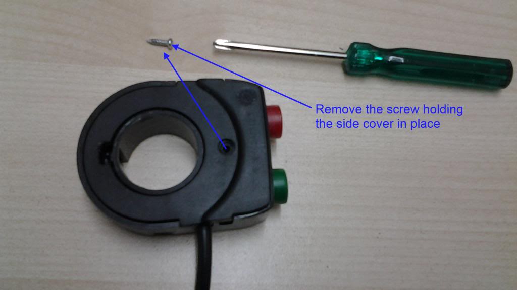
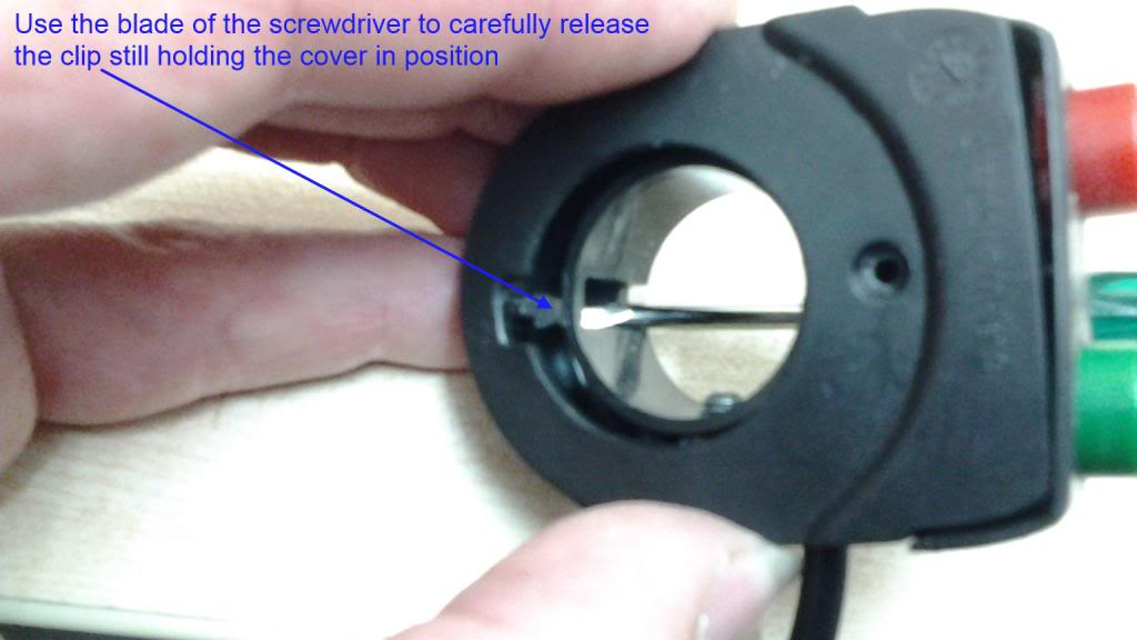
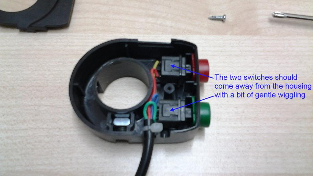
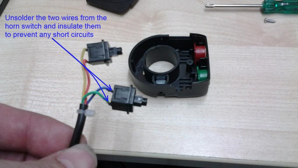
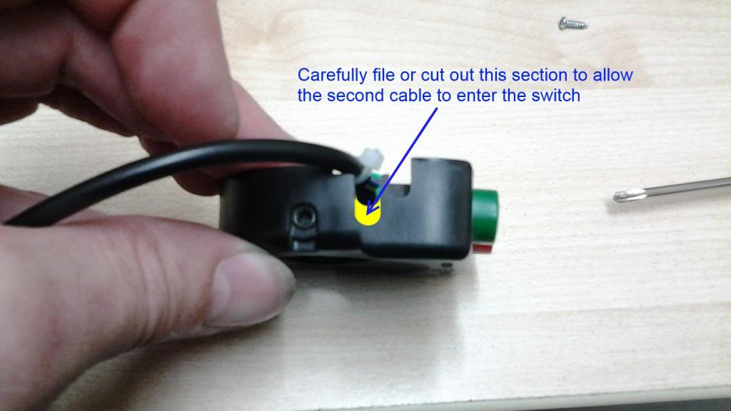
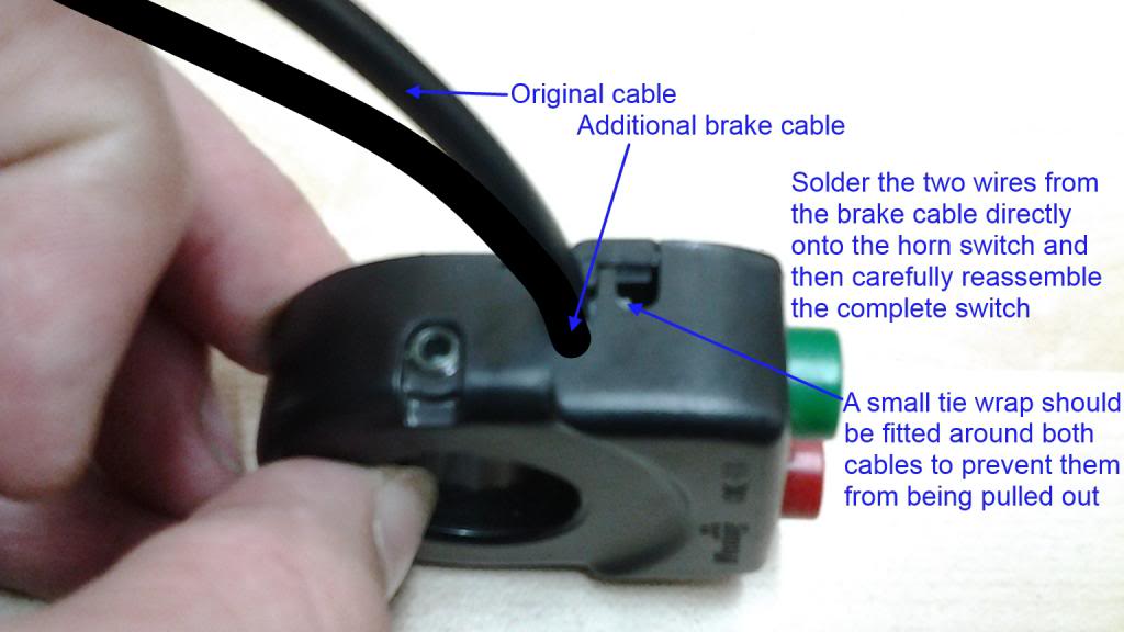
The switch I dismantled was from an early Magic Pie, so the colours of the wires may be different to yours.
The two existing wires going to the horn switch
must both be safely insulated as one of them is connected directly to battery +.
If you prefer to splice the wires in the centre of the cable, the two cut ends of the wires still connected to the switch need to be connected to the two wires in the brake connector cable and it doesn't matter which way round they are connected. If you can stagger the two joins by having slightly different length wires it should make a neater job of the whole joint when either insulation tape or heat-shrink tubing is applied afterwards.
I hope the pictures make it a bit clearer for you.
Elmer,
Although the horn and light units both share a common ground connection, there is no actual ground connection on either the horn or the light switches themselves as they only switch the battery supply to the lights and horn.
Alan