Author Topic: Red Throttle Switch wiring  (Read 11569 times)

Offline RobbyRob

  • Confirmed
  • New Member
  • *
  • Posts: 24
Red Throttle Switch wiring
« on: August 17, 2012, 12:56:08 AM »
Hey would sure love to be able to post in the proper area. Ha ha.

I am new to the forum and have some questions re: Red Throttle Switch wiring.

I am curious if there is a way to wire the switch to an alternate power source say, 12v battery, as I do not wish to draw power from my motor batteries to run my running lights, signal lights etc. on my Pedicab. I currently have a switch for that but the switch on the throttle is more convienient.
Thank you kindly for your knowledge,
Robert

Offline RobbyRob

  • Confirmed
  • New Member
  • *
  • Posts: 24
Re: Red Throttle Switch wiring
« Reply #1 on: August 17, 2012, 01:19:46 AM »
Hello all and thank you for having me.

I simply have a question in RE: to the Red Throttle Button Wiring

Is it possible to wire an alternate power source to the button, say 12v, I have a switch already existing, but it is not convenient for me. The switch operates my LED running lights and signal lights for my Pedicab, The Red switch located on the Throttle would be much more convenient for me. Any replies would be wonderful.

I do understand that the yellow and brown wires are for the switch but not whether they are a positive, negative, ground etc. I also understand that if hooked up to the controller that they will send out 48v to my LEDs which would most likely fry them. So...

I guess the question is If I can by-pass the controller's 48v source and splice my 12v source into the red throttle switch somehow...
« Last Edit: August 17, 2012, 01:22:27 AM by RobbyRob »
Thank you kindly for your knowledge,
Robert

Offline Bikemad

  • Global Moderator
  • Professor
  • PhD. Magic
  • ******
  • Posts: 5,553
Re: Red Throttle Switch wiring
« Reply #2 on: August 17, 2012, 01:20:08 AM »
Hi Robby andto the forum.

Without knowing which motor and controller you have (and the total combined wattage of the 12V lights) it's difficult to say whether the switch can be wired in easily or not.

If you have the latest MPIII style controls, it will not be very easy to access the two wires coming from the switch.

Also, if your combined wattage is more than 25 Watts, then the current required to run the lights may be too much for the switch contacts to handle. However, the switch could be used to control a 12V relay that would then carry the full current that the lighting system requires.

Alan


« Last Edit: July 02, 2017, 09:49:36 PM by Bikemad »

Offline Bikemad

  • Global Moderator
  • Professor
  • PhD. Magic
  • ******
  • Posts: 5,553
Re: Red Throttle Switch wiring
« Reply #3 on: August 17, 2012, 01:32:25 AM »
If I can by-pass the controller's 48v source and splice my 12v source into the red throttle switch somehow...

The Brown and Yellow wires on the early throttles are only connected to the switch contacts and are isolated from everything else inside the throttle control.

If your lighting load is less than 2 Amps, then the switch can be connected (using the brown and yellow wires) in place of your existing lighting switch on the 12V circuit.

Alan


Offline RobbyRob

  • Confirmed
  • New Member
  • *
  • Posts: 24
Re: Red Throttle Switch wiring
« Reply #4 on: August 17, 2012, 01:33:58 AM »
Thanx Allan

I will be running 2 48v 20Ah Lipo4's in Parallel to a Magic Controller V.2 with a Magic Pie II Motor. I currently run the lights off a 12v High Current Car Audio Battery, which I also use for my Sound System. I hope this gives you enough information. As for the total Wattage I am clueless. I just know they all run off one 12v Battery.  :)
« Last Edit: August 17, 2012, 02:54:46 AM by RobbyRob »
Thank you kindly for your knowledge,
Robert

Offline RobbyRob

  • Confirmed
  • New Member
  • *
  • Posts: 24
Re: Red Throttle Switch wiring
« Reply #5 on: August 17, 2012, 01:37:19 AM »
And in response to your last post how would I go about doing that?  Like which Wire is Pos+ and which one Neg-
Thank you kindly for your knowledge,
Robert

Offline RobbyRob

  • Confirmed
  • New Member
  • *
  • Posts: 24
Re: Red Throttle Switch wiring
« Reply #6 on: August 17, 2012, 01:42:36 AM »
Also the diagram is confusing me because the Yellow is soldered to a Neg- and then the Brown goes into the Neg- Battery Post. Do the two wires complete the neg- side of the circuit? If so were does the Positive feed into the switch for the 12v Battery? Meh.. I dunno maybe its not worth the trouble to figure it out, I do not want to blow anything.
« Last Edit: August 17, 2012, 02:52:29 AM by RobbyRob »
Thank you kindly for your knowledge,
Robert

Offline Bikemad

  • Global Moderator
  • Professor
  • PhD. Magic
  • ******
  • Posts: 5,553
Re: Red Throttle Switch wiring
« Reply #7 on: August 17, 2012, 03:11:00 AM »

The colours of the switch wires and their polarity is irrelevant as the switch will work exactly the same, regardless of which way the voltage flows through it, just think of it as being a simple switch with two extension wires connected to it.

Then you simply connect the two ends of the switch wires (the brown and yellow wires) to the two wires going to your existing lighting switch.


Alan
 

Offline RobbyRob

  • Confirmed
  • New Member
  • *
  • Posts: 24
Re: Red Throttle Switch wiring
« Reply #8 on: August 17, 2012, 04:57:42 AM »
I am beginning to understand a bit but allow me to draw a diagram along with yours to help you understand a little better as well. Thank you so much for the electrical 101 lessons, I am a bit slow with electricity :(

I'm just having a hard time understanding.

What I am thinking is to splice the Red and White together on my harness leads. Then brown and yellow and connect the brown and yellow to the black coming from my harness lead. Does that make sense?
« Last Edit: August 17, 2012, 05:40:15 AM by RobbyRob »
Thank you kindly for your knowledge,
Robert

Offline Bikemad

  • Global Moderator
  • Professor
  • PhD. Magic
  • ******
  • Posts: 5,553
Re: Red Throttle Switch wiring
« Reply #9 on: August 17, 2012, 02:01:19 PM »
Robert, your diagram was very useful.

Your light switch has three wires because it has a built in warning light that requires a separate ground connection (the black wire). The two switch contacts are connected to the red and white wires, so splicing them together would simply complete the lighting circuit without a switch, resulting in your lights being on continually.

If you carefully study the following diagram, you will hopefully be able to understand how your existing switch is currently wired, and what needs to be altered to connect the GM throttle switch in place of your existing one:
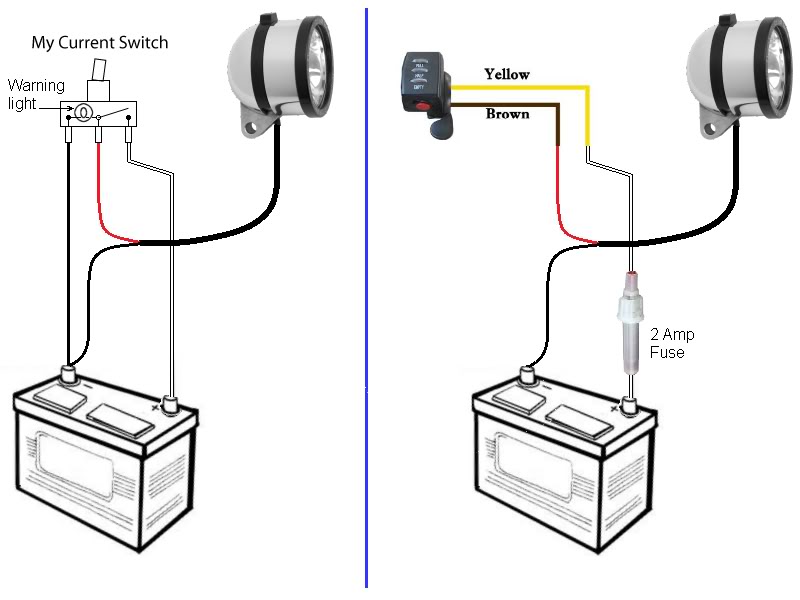


It might be easier to leave the existing light switch in the circuit, and simply join the brown and yellow wires to the red and white wires on the back of the switch. By doing this, your old switch would still light up when the lights were switched on from either switch, but you would also need to make sure that the switches were both in the off position before the lights would turn off.

If your lighting circuit is not fused, I recommend that you fit an in-line fuse to protect the wiring and switches from damage in the event of a short circuit anywhere on the light wiring.

I hope the diagram has made things a bit clearer for you.


Alan
 
« Last Edit: July 02, 2017, 09:49:19 PM by Bikemad »

Offline RobbyRob

  • Confirmed
  • New Member
  • *
  • Posts: 24
Re: Red Throttle Switch wiring
« Reply #10 on: August 17, 2012, 04:55:27 PM »
Alan,

I would like to first off thank you for your time and patience for helping me understand my problem, and how to resolve it. I am very grateful. I rewired the switch as per the drawing (with the 2 amp fuse) and it works like I want it to. Just took some time for me to understand what to do with the 3rd wire  ;) Which was to omit it completely from the switch circuit. Ya Im so excited because the old switch was underneath my machine it was a pain in the but to turn on and off.

If there is anything I can do in the future for you please do not hesitate.
« Last Edit: August 17, 2012, 05:04:16 PM by RobbyRob »
Thank you kindly for your knowledge,
Robert