Author Topic: Magic Pie 4 Brake Wiring  (Read 4681 times)

Offline Pwd

  • Confirmed
  • Bachelor of Magic
  • ****
  • Posts: 151
Magic Pie 4 Brake Wiring
« on: May 31, 2016, 12:48:07 PM »
Hello again,

I am trying to get some after-market brake sensors to work with my Magic Pie 4 so that I can keep my existing hydraulic brake levers. The Magic Pie 4 connector has three wires (red,black,blue) and the after-market sensor has two wires (red and black). The connection I currently have looks like this:

Sensor                 Mp4

Red            ==>  Black
Black          ==>  Red
                           Blue (no connection)


The sensor does stop the throttle but regen doesn't seem to be kicking in. The battery voltage 52.3 V. I had this motor working with regen on a pack with a slightly hight voltage but still under 60V.

Does anyone know if the wiring is setup correctly?

Thanks

Offline Bikemad

  • Global Moderator
  • Professor
  • PhD. Magic
  • ******
  • Posts: 5,519
Re: Magic Pie 4 Brake Wiring
« Reply #1 on: May 31, 2016, 02:09:09 PM »
Paul, that is definitely set up wrong and needs to be sorted immediately (or temporarily disconnected until you get chance to wire it correctly) to protect your controller.

The later Magic Pie brakes have three wires in their cables:


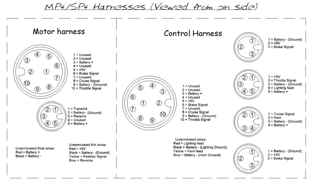
But only two of the three wires are currently used for the brake switch:
   The Black wire is Battery -ve (Ground)
   The Red wire is +5V (which is not currently used)
   The Blue wire is the brake signal which is switched to ground via the switch when the brakes are applied.

The +5V feed is presumably there to allow Hall sensor type switches to be used instead of the mechanical switches that are currently being used.

Your incorrectly wired brake switches are basically shorting out out the +5V feed whenever the brakes are operated and this will be overloading the +5V regulator incorporated into the controller's electronics, which could fail if it doesn't have some form of overload protection.

The only reason the motor it is cutting out when you operate the brakes is because the +5V supply (which is also used for the throttle, pedelec sensor and the motor Hall sensors) is being shorted directly to ground.  :o

As the mechanical brake switches are not polarity dependant, the two wires (Black and Blue) can be connected either way around, but the Red (+5V) wire must be disconnected and safely insulated to ensure it cannot accidentally short out.

With the brake switches wired up correctly, you should find that the regen will work as expected.


Alan
 
« Last Edit: July 04, 2017, 10:17:35 PM by Bikemad »

Offline Pwd

  • Confirmed
  • Bachelor of Magic
  • ****
  • Posts: 151
Re: Magic Pie 4 Brake Wiring
« Reply #2 on: May 31, 2016, 04:23:24 PM »
Thank you for the excellent clarification and explanation Alan.

I had disconnected the brake connector several times when testing yesterday, and I could hear what sounded like a relay switching. That must have been the whole controller powering off and then back on again. I am grateful GM has some sort of protection built in.

I will hopefully get it rewired tonight and try it out.

I owe you one.


Offline Pwd

  • Confirmed
  • Bachelor of Magic
  • ****
  • Posts: 151
Re: Magic Pie 4 Brake Wiring
« Reply #3 on: June 01, 2016, 12:25:51 AM »
I re-wired the sensor to the connector so that the +5v from the controller was not used and the regenerative brake is back in action; just like you thought. 8) Its nice that the two wires are not polarity dependent. I painted the end of the +5v wire with some liquid tape to avoid it shorting out, as you suggested

Thanks for the help

Offline Bikemad

  • Global Moderator
  • Professor
  • PhD. Magic
  • ******
  • Posts: 5,519
Re: Magic Pie 4 Brake Wiring
« Reply #4 on: June 01, 2016, 11:21:27 AM »
I'm pleased that everything is still working and that your controller has survived the ordeal without sustaining permanent damage.

I am grateful GM has some sort of protection built in.

I don't know whether the +5v Regulator is overload protected or whether you have just been fortunate that is was able to withstand being overloaded for intermittent short periods without failing completely. Although most regulator chips seem to have some form of built in over temperature protection, that doesn't necessarily mean that the chip will survive continual short circuit abuse indefinitely.  ;)

Alan