Author Topic: Magic Pie 4 (loom, etc..)  (Read 6707 times)

Offline Luisb

  • Confirmed
  • New Member
  • *
  • Posts: 4
Magic Pie 4 (loom, etc..)
« on: April 19, 2015, 09:17:10 PM »
Hi there,

A couple of weeks I got my self a brand new MP4 and soon I will be starting to assemble everything together.
I'm using some RC Lipo batteries, so I have to do all the wiring my self.

When I received the kit, there is no loom schematics. I can identify easily the power wires and the rest that goes to the front.

But I have one bare cable coming out of the controller with no reference. It's quite short and I have no idea what is for.

There is a second one with 4 small wires inside that comes from the front loom, where the throttle, regen brake wires and cruise connect.

Could some one update the manual for this kit, seems that the user guide for the MP4 is out of date. The pictures don't match my kit and etc..

I want to  plug a temperature display. Is the only way through the cycle Analyst? I don't intend to buy a cycle analyst because I can just plug in a volt, amp and watt meter to my batteries.
So if some one could clarify a little bit the loom situation and if the MP4 comes with a temp sensor inside the controller or the motor, that would be great.

cheers

Offline Bikemad

  • Global Moderator
  • Professor
  • PhD. Magic
  • ******
  • Posts: 5,523
Re: Magic Pie 4 (loom, etc..)
« Reply #1 on: April 19, 2015, 10:24:57 PM »
Hi andto the forum.

The MP4 harness connections are similar to the MPIII shown here:


The main difference being the multiblock connector is different:


And the 8 pin connector on the old harness has been replaced by a 10 pin connector on the new harness:


The four small wires on both of the cables perform exactly the same function on early and later style harnesses (lights, horn, reverse and pedelec).

If you are not using these eight wires I suggest you make sure that they are safely insulated, as the individual wire's insulation will shrink back over time and allowing the inner copper wires to be exposed which can then cause unwanted short circuits.

If you want a fit temperature display you will need to fit a suitable sensor somewhere inside the hub as there is no temperature sensor on the motor windings. I have had a good look but I can't even see the temperature sensor that is supposedly integrated into the controller. I think it must be located on the lower circuit board which you are unlikely to access without damaging the controller.

As you are using LiPo batteries, I strongly recommend that you fit a 30 Amp fuse. ;)


Otherwise there is nothing to limit the current if something shorts out:


Alan
 
« Last Edit: November 23, 2020, 10:25:25 AM by Bikemad »

Offline Lewis Balentine

  • Confirmed
  • Junior Member
  • **
  • Posts: 37
Re: Magic Pie 4 (loom, etc..)
« Reply #2 on: April 19, 2015, 11:38:23 PM »
"And the 8 pin connector on the old harness has been replaced by a 10 pin connector on the new harness:"

What are the two extra wires used for ?

Offline Mgizen

  • Confirmed
  • Junior Member
  • **
  • Posts: 36
Re: Magic Pie 4 (loom, etc..)
« Reply #3 on: April 20, 2015, 04:43:14 AM »
On this topic should I be running some kind of fuse with my GM 48v 10ah battery and MP4. I just connected the battery connector to the motor battery leads and have been running it like that? Any ideas?
thanks

Offline Luisb

  • Confirmed
  • New Member
  • *
  • Posts: 4
Re: Magic Pie 4 (loom, etc..)
« Reply #4 on: April 20, 2015, 05:54:31 AM »
Bikemad,

thank you so much for your help. Indeed, the looms are the same. That solved my problem.
I was thinking about the 30 amp too. I got a fuse holder just like that one you showed.

Mgizen,

I don't think you need. I don't know much about the battery kits from GM but I assume that they have a BMS integrated inside and maybe a fuse. Normally people don't have to do extra mods on those packs. But I can't be sure if they have a fuse or not. Even after all you should be fine.

Bikemad,

I have a couple of doubts. I'm not an expert on this ebike thing. I don't know if you can help me.
I posted at the endless sphere forum a couple of questions and maybe some one could help me here too. Automatically, my ignorance was bullied by some expert.

Here's a part of my post:

"I know that the RC batteries have 2 rates for the current discharge. Maybe I will find out how this works when I start to play with the controller software but...
How do I use the peak discharge from the lipos for those 10 or 20 seconds? Do I have to install a button and set two modes in the controller? If yes, where do I plug that switch?
I know that is up to the motor and the controller to assume how much current is needed but I need some help to understand why there is a 20C and 30C rate and how do I control that (if possible). Because if the normal rate is 20C, then I won't have 15Ah constant. I would have 20x that instead which seems impossible to me because the controller and the motor wouldn't handle that much."

I just don't understand much about the discharging rate. I read some articles but none answered my questions.
I'm using a 3s3p lipo rc battery pack. With this ones: http://www.hobbyking.com/hobbyking/store/__15521__Turnigy_5000mAh_4S1P_14_8v_20C_Hardcase_Pack.html

I saw once a topic with a guy that was using rc lipo batteries and because he was using the peak discharge, he had to increase the fuse capacity to 80 amps.
I just don't get how he was using that peak, seems that every one else just connects the rc lipo batteries and they work with a 1C discharge rate.

If this is offtopic, I don't mind to create a new thread.

Thank you.

Offline Bikemad

  • Global Moderator
  • Professor
  • PhD. Magic
  • ******
  • Posts: 5,523
Re: Magic Pie 4 (loom, etc..)
« Reply #5 on: April 21, 2015, 12:58:56 AM »
"And the 8 pin connector on the old harness has been replaced by a 10 pin connector on the new harness:"

What are the two extra wires used for ?


As far as I am aware they are not used for anything at the moment, but it would have been a good idea to use them to double up on the battery feed to the lighting switch and the battery ground wire.
This would reduce the voltage drop along those wires when using higher wattage LED headlamps.  ;)

On this topic should I be running some kind of fuse with my GM 48v 10ah battery and MP4. I just connected the battery connector to the motor battery leads and have been running it like that? Any ideas?
thanks


The GM battery will be fine without a fuse as the BMS should prevent excessive current from being delivered.
With a home made LiPo pack it is very important to use a fuse to protect against cable damage from excessive current and also to protect the battery itself in the event of a short circuit.

I posted at the endless sphere forum a couple of questions and maybe some one could help me here too. Automatically, my ignorance was bullied by some expert.

You were not bullied, you were simply given some very good advice regarding the big difference between cells and batteries because you will need to know this sort of basic information in order to accurately describe exactly what you are trying to achieve.

"I know that the RC batteries have 2 rates for the current discharge. Maybe I will find out how this works when I start to play with the controller software but...
How do I use the peak discharge from the lipos for those 10 or 20 seconds? Do I have to install a button and set two modes in the controller? If yes, where do I plug that switch?
I know that is up to the motor and the controller to assume how much current is needed but I need some help to understand why there is a 20C and 30C rate and how do I control that (if possible). Because if the normal rate is 20C, then I won't have 15Ah constant. I would have 20x that instead which seems impossible to me because the controller and the motor wouldn't handle that much."

I just don't understand much about the discharging rate. I read some articles but none answered my questions.
I'm using a 3s3p lipo rc battery pack. With this ones: http://www.hobbyking.com/hobbyking/store/__15521__Turnigy_5000mAh_4S1P_14_8v_20C_Hardcase_Pack.html

I saw once a topic with a guy that was using rc lipo batteries and because he was using the peak discharge, he had to increase the fuse capacity to 80 amps.
I just don't get how he was using that peak, seems that every one else just connects the rc lipo batteries and they work with a 1C discharge rate.

It is very clear from your post that you still have a lot to learn about batteries and perhaps the basics of electrical current too. ;)

First let's start with your battery pack:
The individual LiPo packs that you are using each contain 4 cells, but hopefully not all puffed up like these:


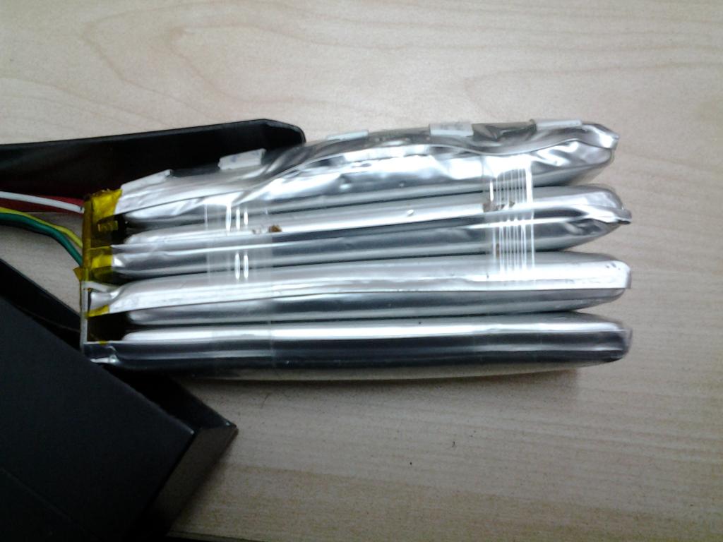
It is commonly referred to as a 4S1P pack because it has four individual cells (1P) connected in series.
If it were a 4S2P pack it would have 4 pairs of 2 parallel cells (2P) connected in series.

This is what a 3S3P battery pack looks like:


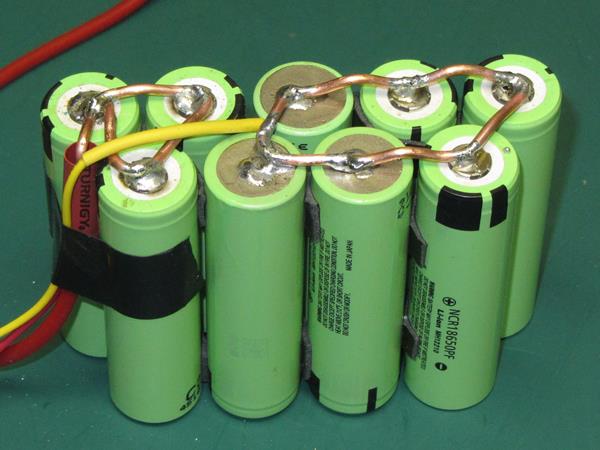
It has a nominal voltage of 11.1V (3 x 3.7V cells in series) and a capacity of 8.7Ahs (3 x 2900mAh cells in parallel).

But your pack will be configured as 12S3P with a nominal pack voltage of 44.4V and a total capacity of 15Ah.
The 20C continuous rating means that your pack is theoretically capable of supplying 300 Amps (not Ah) continuously  and the 30C peak means that if the load applied was high enough it could supply 450 Amps for 10-20 seconds without damaging the cells.

The Magic Pie 4 controller is unable to draw more than around 30 Amps of current from your pack (2C) because the power taken from the battery is limited by the maximum power of the controller and motor.

It's a bit like a 60Ah 12V car battery that can supply 100's of Amps to crank a big diesel engine, but if you connect a low power device across the terminals (like a 12V 5 watt bulb) it would only deliver 0.42 of an Amp
If you connected two 60 watt headlamp bulbs in parallel across the same battery it would instantly deliver 10 Amps of current to light up the bulbs.

So you don't need to worry about the maximum 20C (300 Amps) as you will never require it. Fitting a 30 Amp fuse will ensure that this will never happen, even if the battery power leads are accidentally shorted.

LiPo batteries can be very dangerous and therefore require great care when you are connecting the wires during assembly of the pack. Plugging the wrong connectors together can result in severe burns and the risk of the battery pack exploding into a fireball.
Overcharging a LiPo pack can transform it into a very destructive incendiary device, and houses and sheds etc. have been completely destroyed by fire as a direct result!

I strongly advise you to read the warning label on the battery very carefully, especially the bit that says, "Always charge in a non-flammable area" and "Never leave a charging battery unattended".

Just to give you some idea of what can happen, take a look at this video showing 2 x 5000mAh cells exploding, and then consider that your battery will contain 36 of those cells in very close proximity!

Regarding your question about using two power supplies for faster charging, if some cells become weaker than the others the battery will become unbalanced, a higher charging current will cause a much higher voltage difference between the weaker and stronger cells.
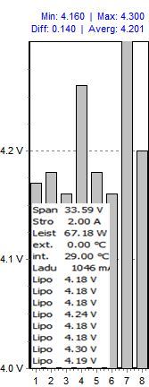
Here you can see the result of a poor pack with unbalanced cells during a normal (non-balanced) charge and the charging current is only 2 Amps:


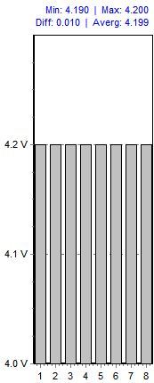
And this shows what it should look like with a good pack during a balanced charge:


Having said that, two of those power supplies in parallel would be charging at a maximum of 14.6 Amps, which is still less than 1C for a 15Ah pack.

One thing that you mentioned on your Endless-Sphere post has me puzzled; "The controller has it own low voltage switch, very handy."
Which switch are you referring to?

Alan
 
« Last Edit: July 02, 2017, 11:16:00 PM by Bikemad »

Offline Luisb

  • Confirmed
  • New Member
  • *
  • Posts: 4
Re: Magic Pie 4 (loom, etc..)
« Reply #6 on: April 21, 2015, 02:58:05 AM »
Hi Bikemad,

thanks again for your effort and patience to explain step by step.

Indeed my post at ES is not the best. English is not my mother language and the way I explain things are wrong. I now from the beginning the difference between a battery and a cell.
One of the guys did help. I believe that questions are never stupid but answers sometimes can be.

I assume that I don't know anything about electricity and electronics. I don't have any background or studies in that area.

That's why I appreciate a lot any help from some one that can teach me the basics and help to guide me through.

When it comes to handle Lipos. That's the first thing I manage to understand. Security first and my charging base will be a pyrex glass base on a cement area just outside my living room. I can watch them and it's safe.
I'm ok with being picky and measure the cells all the time. Looking after them and balancing will be part of my daily tasks. The BC 168 manual is very good in explaining how to use the charger properly and how to use in a way to keep the cells healthy and last longer.

And the best part, is that you could explain me the C rate in ways that I could understand. Thank you so much for that.
I always assumed that the motor and the controller would demand a certain amount of current.
I read articles of people saying that they can control that with a switch. Maybe possible in their system. But not with the MP4.

Now I just have a question.

"Having said that, two of those power supplies in parallel would be charging at a maximum of 14.6 Amps, which is still less than 1C for a 15Ah pack."

I'm happy if I'm close to 1C. The Lipo cell manual says that I shouldn't charge more than 1C. What could be a good value to charge?

"Which switch are you referring to?"

I think the way I explain is wrong and I'm talking about something that I'm might be wrong too.
I'm talking about the grey button under the throttle nob. It's a two position switch that I assume (maybe wrongly) that was a on/off for the controller. Not a voltage switch.
It could be for the lights like the MP3 but in a new format.
Sorry if I assume this wrong. My bad.

Again and again, thank you for all your patience. I'm here to learn.

cheers!