Author Topic: HPM-3000B BLDC 72V motor and VEC220 72V problem  (Read 8398 times)

Offline Gegs

  • Confirmed
  • New Member
  • *
  • Posts: 2
HPM-3000B BLDC 72V motor and VEC220 72V problem
« on: February 01, 2017, 11:59:39 PM »
Hello,

I wish to be a member as I have found some very good information and thank. I plan to build an electric bike and I hope I can help others in the future. However I do have a problem with my new gear.

I have purchased a new HPM-3000B BLDC 72V motor, VEC220 72V Sine-wave controller, throttle grip, 72V contactor, basically a complete system from Goldenmotors to build an electric motorbike. I am at the stage of bench testing the equipment and programming the controller as per the attached picture. I am monitoring the input voltage and current and I am able the measure the output to the motor as well.

I am having a few problems with bench testing the system. Can someone please help?

1.   I tested 72volt 400A MZJ-400A contactor, by applying 72volts between A1 and A2 terminals and there is no continuity between the main contacts when energised. I can hear the contactor click when power is applied, however it does not work. Please advise if you have any suggestions to why it does not work would as it would be appreciated.

I omitted the contactor as it does not work and wired up the system as per the Goldenmotor wiring diagram however it does not work properly. The motor sometimes runs for 3-5 seconds then stops or it will not start. Or when it does not start I rotate the motor rotor and give it another go and it will start however it only runs for 3-5 seconds then stop and sometimes it will surge for 3-5 seconds then stop.

What I have tried:
2.   I have programmed the VEC220 Sine-wave Controller configuration for 72 volts, this is listed below and could you please check my setting to see if they are correct for the 3kW motor running at 72 volts and VEC220 controller type please? I am not sure if it is a 5 pole motor? Also I am not sure on the rest of the setting they seem correct but there is no documentation to check it against. I have been able to upload and down load the configuration several times with no problems and the same configuration is being stored in the controller. I believe it is holding the setting correctly. I am not sure if the pole pairs are correct for this motor type? Or if the other settings are correct?

3.   I have done an individual throttle test and applied 5 volts input to the throttle and with minimum input output was 0.84volts and at maximum it was 4.26 volts. I believe this is working correct for a hall throttle type from some other posts in this forum. Is this correct?

4.   I measured the hall sensor outputs. By disconnecting the motor Phase wires U (yellow), V (green) and W (blue) so the motor will not rotate with power applied to the controller and I measured the hall sensor voltages between the black wire and to the blue, green and yellow, while rotating the motor manually I was getting each Hall sensor measuring around 4.0 to 4.8 v and dropping to 0 volts as I rotated the rotor manually. I roughly marked a piece of paper to when each of the hall sensors were firing and they seem to working ok. I might do a more accurate measurement if required. I have a pic of the paper markings and have electrically measured a 1/4 turn of the motor shown as a time plot. Where Hall wire yellow-Chan A- Blue marking, Hall wire blue-Channel B- red markings, Hall wire green-Chan C- Black marking.

This is all the information I have at the moment and will further read up and fault find. If someone could check the VEC220 controller setting or have any other recommendations that would be greatly appreciated.

Thank you
Adam

Vector Controller 72V220 Software Configuration using the PI-800 software version v3.3v0.v150501
Motor Parameters
Hall electrical angle      120
Phase angle offset      120
Number of pole pairs      5
Rated motor speed (rpm)   6000

Voltage Parameters   
Nominal battery voltage (V)         72
High voltage protection (V)         90
High voltage protection exit value (V)      86
Minimum work voltage (V)         50
Low voltage protection value (V)      63
Low voltage exit value (V)         2
Low voltage protection enable         0:Disable
Low voltage triggering current reducing (V)   66
Clear under voltage state while throttle off   0:Disable

Current parameters settings
Starting phase current (A)      25
Maximum  phase current (A)      220
Maximum phase current duration (s)   10
Rated phase current (A)         200
Battery drawn current limit (A)      80

Temperature Settings
Motor over temperature protection enable   0:Disable
Motor current limit temperature limit 1      120
Motor current limit temperature limit 2      130
Maximum motor protection temperature   150
Maximum motor protection exit value      20

Motor Blockage settings
Motor blockage protection enable   1:Enable
Stall protection time (s)         2

Throttle parameters settings
Throttle voltage range protection enable   1:Enable
Throttle mode selection            0:Hyperbola
Throttle maximum allowed voltage (V)      4
Throttle upper voltage fault exit value (V)    3.5
Throttle lowest allowed voltage fault exit value    0.4
Throttle lower voltage maximum valid voltage   0.7
Throttle maximum valid voltage (V)      3.2
Throttle minimum valid voltage    (V)      1.2

Accel abd Decel parameters settings
Acceleration (rpm/s)   600
Deceleration (rpm/s)   600

Warrenty date   201512
Software version    1201


Controller function settings
Regenerative braking
EBS enable      1:Enable
Reverse charging voltage (V)    86
Reverse charging current (A)    60
Enable EBS Auto mode      0:Disable
EBS Auto_Mode Speed (rpm)   450

Cruise Control settings
Cruise Control enable            0:Disable
Cruise Control manual mode enable      0:Disable
Cruise Control Automatic mode enable      0:Disable
Cruise mode throttle minimum voltage (V)    1.5
Cruise mode throttle minimum voltage (V)    30
Automatic cruise response time (s)       8

Fwd-Speed_Loop setting
Forward speed ratio      85

Bwd-Speed-Loop setting
Backward speed ratio (%)   100
Reverse torque ratio (%)   100

3-Gear Func setting
3-Gears enale         0:Disable
3-Gear switch mode setting   0:Button
Default gear (0:HG 1:MG 2:LG   0
High speed ratio (%)      100
Mid speed ratio (%)      80
Low speed ratio (%)      60

Boost Func setting
Boost enable      0:Disable
Boost mode       0:Manual mode
Boost current (A)   80
Boost keeping time (s)   20
Boost interval time (s)   90

Speed throttle type   0:Hall effect throttle


Offline Bikemad

  • Global Moderator
  • Professor
  • PhD. Magic
  • ******
  • Posts: 5,499
Re: HPM-3000B BLDC 72V motor and VEC220 72V problem
« Reply #1 on: February 02, 2017, 12:05:17 PM »
Hi Adam andto the forum.

1. It sounds like the problem is with the electrical contacts inside the contactor not making a good connection when the solenoid plunger is energised. As most contactors are sealed units, it may need to be replaced.
You can try operating it intermittently (lots of times) to see if the continuous movement will eventually clean the contact surfaces, but if it's caused by plastic debris trapped between the contacts, you may find that it won't make any difference.

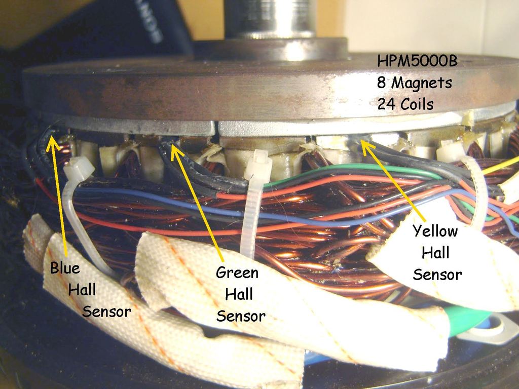
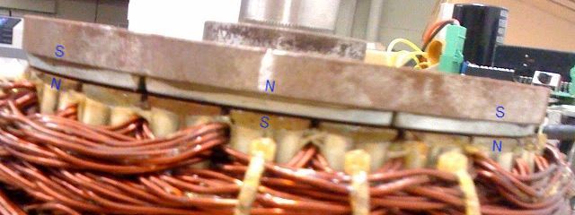
2. I suspect the HPM3000B has 8 magnets (4 pole pairs) the same as the HPM5000B, and your Hall sensor markings would also seem to indicate that there are 4 pole pairs.


Set the "Number of pole pairs" parameter to 4 and see if it sorts your problem.

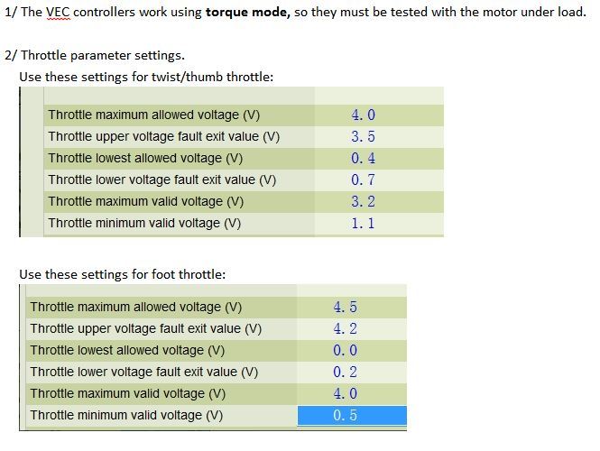
3. Your throttle seems to be working correctly and your throttle parameters seem to be correct for a twist throttle:


4. From what I can see, the Hall sensors all appear to be working correctly, but in a slightly difference sequence (G-Y-B) compared to the HPM5000B (Y-G-B) for clockwise rotation.

Hopefully, entering the correct number of pole pairs will cure the problem.


Please let us know if this works.

Alan
 
« Last Edit: July 04, 2017, 08:30:52 PM by Bikemad »

Offline Gegs

  • Confirmed
  • New Member
  • *
  • Posts: 2
Re: HPM-3000B BLDC 72V motor and VEC220 72V problem
« Reply #2 on: February 03, 2017, 03:41:03 AM »
Hello and thank you for allowing me into the group.

Thank you for the comprehensive reply, greatly appreciated.

I tried to change the VEC220 controller motor settings to 4 pole pairs however it is not allowing me to change it and it keeps reverting to 5 pole pairs.

I did some free wheeling of the motor to record each of the three motor yellow, blue, green drive wires to measure the back emf with the controller disconnected to get a hall sensor to power cable winding voltage relationship to see if it is wired correctly.
I am going down the track that the hall sensors might be wired wrong and I want to check to the electrical wiring and timings to see if they are correct… Nothing sure yet. I become a little aware after you mentioned the difference to the HPM-5000 as I would have thought the wiring configuration would be the same.

Well I have more testing and research to do.

Thanks again for your help, I will post more information once I have done some more testing.

Cheers
Adam

Offline Bikemad

  • Global Moderator
  • Professor
  • PhD. Magic
  • ******
  • Posts: 5,499
Re: HPM-3000B BLDC 72V motor and VEC220 72V problem
« Reply #3 on: February 04, 2017, 01:45:09 PM »
From what I can see, the Hall sensors all appear to be working correctly, but in a slightly difference sequence (G-Y-B) compared to the HPM5000B (Y-G-B) for clockwise rotation.

I become a little aware after you mentioned the difference to the HPM-5000 as I would have thought the wiring configuration would be the same.

I have just double checked the sequence for clockwise rotation and it does appear to be the same as the HPM50000B.

In the clockwise direction, your test results indicate they operate in the following order:
Black --> Red --> Blue markings which equates to Green --> Blue --> Yellow Hall sensors.

Green --> Blue --> Yellow, Blue -->Yellow --> Green, or Yellow --> Green --> Blue are all the same sequence as the Y-G-B of the HPM5000B.
Sorry if I have caused any unnecessary inconvenience, I must have somehow got the pen colours and the Hall sensor colours mixed up in my head. ::)
I used a pen and paper this time to avoid any more mistakes.  ;)

I tried to change the VEC220 controller motor settings to 4 pole pairs however it is not allowing me to change it and it keeps reverting to 5 pole pairs.

Are you able to change and save correctly all the other parameters, or do they all return to their original values too when you read the parameters again after saving them?

Alan