Author Topic: ON/OFF Switch to the controller  (Read 22203 times)

Offline Ecobully

  • Confirmed
  • Junior Member
  • **
  • Posts: 29
ON/OFF Switch to the controller
« on: February 02, 2016, 03:34:51 AM »
I would like to setup an on/off switch near or on the throttle. There are some keyed throttles now available so that I will not have to unplug power from the battery pack or wiring it so that it requires large gauge wires to my throttle.

Simple.. where to wire it on the controller so that it can be turned off and subsequently stops power from going to the motor. The current way I have it setup is similar to an emergency shutoff and not very elegant and not very thought out--barbaric with sparks!

Offline NR

  • Confirmed
  • Junior Member
  • **
  • Posts: 29
Re: ON/OFF Switch to the controller
« Reply #1 on: February 02, 2016, 08:35:34 PM »
I'm not sure its the solution you want, but I have routed the 5v powerline to the throttle sensor via the light switch, and removed old wires from the switch, and isolated the wire coming from battery (36-54V). When switch is deactivated throttle doesnt work, but brake/regen work, and electronics is still alive showing battery voltage.
Also works as a simple antitheft switch if no pedelic is connected.  ;)

Offline Ecobully

  • Confirmed
  • Junior Member
  • **
  • Posts: 29
Re: ON/OFF Switch to the controller
« Reply #2 on: February 05, 2016, 12:39:41 AM »
Thanks NR.

Not quite the solution that I had in mind, but it's still one step towards a safer bike (especially when it's parked). I currently use a non-spark XT90 connector to "unplug" from the battery to cut off the power. I also have a Crystalyte key switch that does basically the same thing with added sparks.

Offline Bedmountain

  • Confirmed
  • Magic Undergrad
  • ***
  • Posts: 92
Re: ON/OFF Switch to the controller
« Reply #3 on: March 02, 2016, 12:29:37 PM »
I'm trying to get my head around this at the moment but as usual I'm a little confused...

I've just replaced my battery (GM battery with key switch) for a battery with no switch.

I was going to simply attach a XT90 anti-spark female plug to the red and black leads from the battery and the male end of the plug to the red and black wires from the controller.

Is this a safe and practical solution? Ideally I'd prefer a switch somewhere but not sure the best point in the wiring to install it and from reading other posts it doesn't seem that simple if I want to avoid sparking?

If anyone could describe a safe switch solution for turning the battery off that an electrical dumbo like me can understand that would be awesome :)...

Offline Bikemad

  • Global Moderator
  • Professor
  • PhD. Magic
  • ******
  • Posts: 5,499
Re: ON/OFF Switch to the controller
« Reply #4 on: March 02, 2016, 09:34:45 PM »
The XT90 anti-spark connector should work fine, but if you want a separate switch it might be a good idea to incorporate a simple push button switch combined with an On/Off switch to enable the power to be turned on when the battery is already connected without the switch contacts sparking each time.

I have shown a basic layout below showing how the switches and precharge resistor should be wired:


The double pole rocker switch has both sets of contacts connected in parallel to enable it to switch twice as much current as both set of contacts will be equally sharing the total current flow.
This means that a single double pole switch with a contact rating of 16A can handle 32A when the current is split between both sets of contacts.

Check out this post for more details on the switches.

1 watt resistors between 10 and 100 Ohms seem to work nicely with 24V, 36V and 48V batteries, but if you have LED lights fitted, make sure they are turned off prior to precharging the controller to prevent the resistor from being unnecessarily overloaded when the precharge button is pressed.

If you only have ΒΌ Watt resistors, you can simply use four resistors wired in a series parallel configuration to produce the same value resistor that can carry four times as much current:


Also, do not try to operate the throttle if the battery is only connected through the precharge resistor as the high current will very quickly cook the resistor!

If you would like more specific resistor values, check out this link.

Alan
 
« Last Edit: July 03, 2017, 09:29:11 PM by Bikemad »

Offline RooGM

  • Confirmed
  • Magic Undergrad
  • ***
  • Posts: 58
Re: ON/OFF Switch to the controller
« Reply #5 on: March 03, 2016, 01:12:19 AM »
As Alan has explained, the pre-charge button method is a good way to go.  I tried several high current switches on my system and all of them would stick in the on position internally even when the level is thrown back to off.  They just can't handle the high current and big spark and the contacts would often stick, requiring some wiggling back and forth of the switch lever to power off again.

Offline Bedmountain

  • Confirmed
  • Magic Undergrad
  • ***
  • Posts: 92
Re: ON/OFF Switch to the controller
« Reply #6 on: March 03, 2016, 01:18:01 PM »
Absolutely brilliant help as usual Alan - thanks very much.

I can only find 33 ohm resistors on my favourite auction site which I guess is fine?

Also - I'm pretty sure the resistor in your diagram is soldered to the 'off' position on the rocker switch but just want to check that's the case.

Offline Bikemad

  • Global Moderator
  • Professor
  • PhD. Magic
  • ******
  • Posts: 5,499
Re: ON/OFF Switch to the controller
« Reply #7 on: March 04, 2016, 12:22:10 PM »
A single 33 Ohm 1 Watt resistor should be fine, but you could use four 1/4 Watt resistors connected in a series parallel configuration instead:


The rectangular DPST switch shown in the diagram only has four contacts (two contacts for the input and two contacts for the output):


Click Here for more details


The resistor (wired in series with the push button switch) is connected across the Input and Output connections as shown in this circuit diagram:


Pressing the button for a couple of seconds allows limited current to flow between the Input and Output contacts on the Power switch to precharge the capacitors inside the controller and reduce the voltage difference across the power switch contacts.
This allows the power switch to then be turned ON without any arcing across the switch contacts, because they should already be at a similar voltage.

When the switch is in the OFF position, the input and output terminals are not connected together inside the switch, but in the ON position, all four terminals are effectively joined together by the two pairs of switched contacts inside the switch and the parallel loop wiring connections on the outside of the switch.
Connecting the switch contacts in parallel effectively doubles the amount of current that the switch can handle, therefore a 20A switch should be able to cope with a 40A load.

The switches and resistor can either be fitted on the battery side of the connector, or the motor side of the connector.

If you have just one battery that is used on two or more eBikes, it would be better to have the switches combined with the battery pack, otherwise you would need to fit one set of switches on each bike, but if there's just one battery and one eBike, you will probably have a lot more space to mount the switches on the bike itself.

Another alternative would be to have a separate switch unit that can plug between the battery and motor harness, but this would require two pairs of high current connectors instead of just one.

Alan
 
EDIT: Broken link repaired
« Last Edit: August 01, 2022, 09:42:27 AM by Bikemad »

Offline Bedmountain

  • Confirmed
  • Magic Undergrad
  • ***
  • Posts: 92
Re: ON/OFF Switch to the controller
« Reply #8 on: March 04, 2016, 12:55:39 PM »
Got it! - thank you Alan.
I'd completely misunderstood what was going on inside the switch.
I've ordered the parts and look forward to posting the details of how many things I manage to c :o ck up carrying out a task most primary school children could manage  ;D

Offline Bikemad

  • Global Moderator
  • Professor
  • PhD. Magic
  • ******
  • Posts: 5,499
Re: ON/OFF Switch to the controller
« Reply #9 on: March 04, 2016, 05:03:55 PM »
I'd completely misunderstood what was going on inside the switch.

Sorry Ben, if I'd posted the correct circuit diagram in my last response (see revised post) it might have been even easier to understand.

Alan
 

Offline Ecobully

  • Confirmed
  • Junior Member
  • **
  • Posts: 29
Re: ON/OFF Switch to the controller
« Reply #10 on: March 04, 2016, 09:07:09 PM »
@Alan,

Any idea where to start with adding a switch to the low power controller on/off wires? I understand that I'll need to do some surgery inside the controller area of the hub motor. I would like to add a power switch (or two) near the handle bars and didn't want any high current wires nearby in case of a crash.

Offline Bikemad

  • Global Moderator
  • Professor
  • PhD. Magic
  • ******
  • Posts: 5,499
Re: ON/OFF Switch to the controller
« Reply #11 on: March 05, 2016, 01:59:01 AM »
There are no on/off low power wires feeding the controller as the thick battery wires go direct to the motor controller circuit board and there is no practical way of isolating either the +12V supply used for switching the FETs, or the +5V supply for the Hall sensors in the motor, throttle and pedelec sensor, both of which are integrated into the main controller PCB itself.

While the battery is connected and turned on, the circuit board will be continually powered up and drawing a small amount of current.  You will also have a battery voltage supply going directly to the throttle unit in order to supply the LED battery gauge, which will also remain lit and drawing a small amount of current while the battery is connected.

As suggested earlier by NR, you can switch the +5V supply going to the throttle in order to disable the motor power, but the controller will remain powered up and the battery gauge LEDs will remain illuminated.

On one of my bikes, I wired the light switch on the throttle to activate the regenerative brake when it was pressed in, and this prevents any unwanted motor activity if the throttle is accidentally operated while manoeuvring the bike etc.

One way to incorporate a low current power switch (or two) near the handlebars would be to install a separate battery feed to operate a high current relay connected to the battery wires:


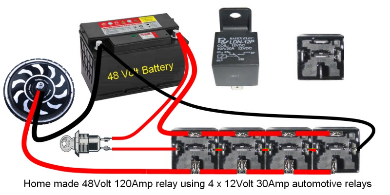
Alternatively, instead of using four 12V relays wired in series with paralleled contacts as shown above, you could install a single 48V 40A relay or a step down DC/DC converter with its output set to 12V to power a single 12V 40A relay:


The 12V output of the inverter could even be used to power a 12V remote control switch unit:


This remote switch unit could then be used to switch the 12V 40A relay.

The following remote switch would also require the 12V inverter output to power it from the bikes battery:


But it would not need an additional 12V 40A relay as the onboard 30A relay should be adequate for a Magic/Smart Pie on its own.

Unfortunately, using a 12v inverter to power the remote receivers means that it would continually draw a small amount of current even when everything was switched off.

Using the inverter and relay would continually draw a small amount of power while the relay was energised, but if the on/off switch was used to supply battery voltage to the input side of the inverter, at least it would not consume power when it was turned off.

I wish someone would produce an inexpensive 24~60V high current latching relay that could be controlled by a flip flop action using a single momentary push button switch, and preferably with an integrated automatic precharge function.  :D

Alan
 

EDIT: Broken links repaired
« Last Edit: August 01, 2022, 11:36:52 AM by Bikemad »

Offline Ecobully

  • Confirmed
  • Junior Member
  • **
  • Posts: 29
Re: ON/OFF Switch to the controller
« Reply #12 on: March 05, 2016, 09:41:08 PM »
Alan,

Thanks! I will take your advice and start on something similar to what you posted. What an amazing reply to my inquiry! For now, a high amperage circuit breaker has been durable enough as a master on/off switch near the battery pack.

I am also considering other motors and controllers that has this feature out of the box (btw, not too many).

Offline Bedmountain

  • Confirmed
  • Magic Undergrad
  • ***
  • Posts: 92
Re: ON/OFF Switch to the controller
« Reply #13 on: March 19, 2016, 11:08:27 PM »
Just a quick post to show the results of my labours after Alan's excellent post.

I struggled a bit with the soldering around the 4-way switch. In hindsight and with a bit more forward thinking (both of which I try and avoid) I should have probably used a single wire through the poles or soldered some kind of bar across the poles that needed connecting? I'm not sure - I used separate wires because that's what it looked like in Alan's picture  :D.

Not my finest hour with a soldering iron but it was freezing in the shed and my hands were shaking and....  Who am I kidding - I'm still just a real noob with a soldering iron  :-[.

Anyway - the real reason for this post is to show Alan that all his hard work and the effort he puts into his posts does actually result in someone doing something with the info and that he's not wasting his time...

It might not work (I don't have a battery at the moment) - but that will be due to the execution and not the theory.

Without Alan's support over the last 2 years I would still be sitting in my shed randomly hitting my Magic Pie 3 with a mallet in the hope I could get it going again - thanks Alan - you are the heart and brain of this forum and it's much appreciated...

p.s - don't laugh at my little tupperware box - It's watertight and with a bit of duct tape and maybe a skull and crossbones somewhere it will look much more manly...


Offline Klatuu

  • Confirmed
  • New Member
  • *
  • Posts: 9
Re: ON/OFF Switch to the controller
« Reply #14 on: April 08, 2016, 07:57:44 PM »
What method do the manufacturers of batteries with key switches use?  Seems like they must use a simpler system than all of this.