Hello all,
It seems there is a need for a little guidance in setting up this motor and controller combination. So here is my first test setup
Here are the components I used for this test.
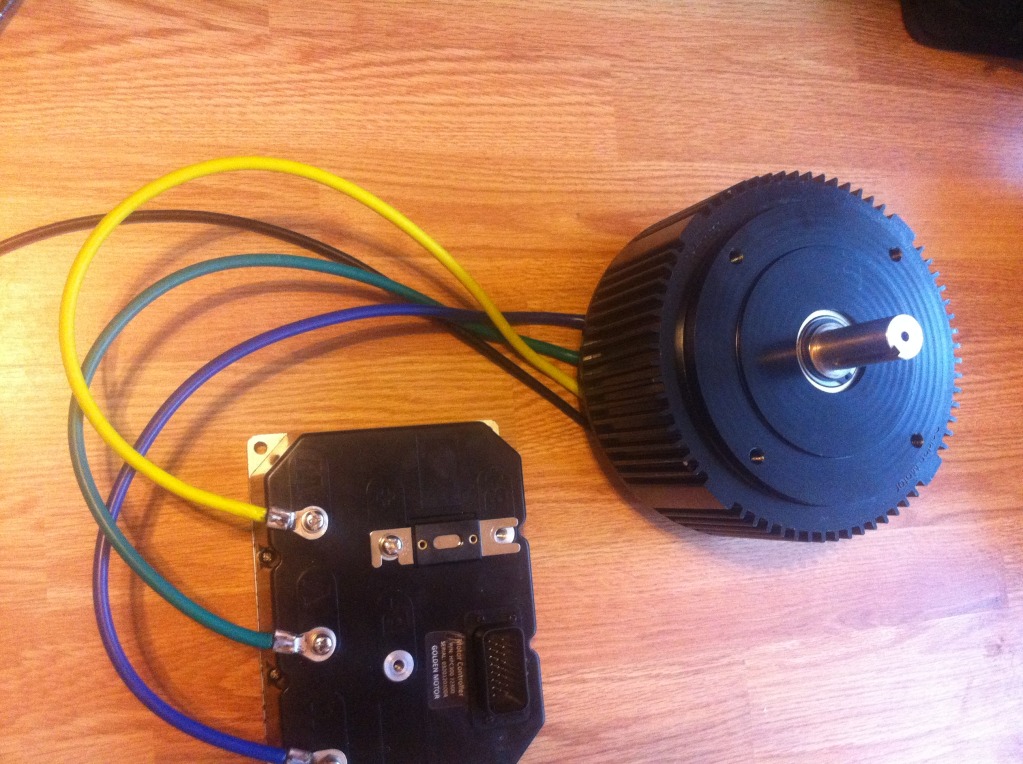
HPM5000B Motor
HPC300 Controller (comes with wire harness)
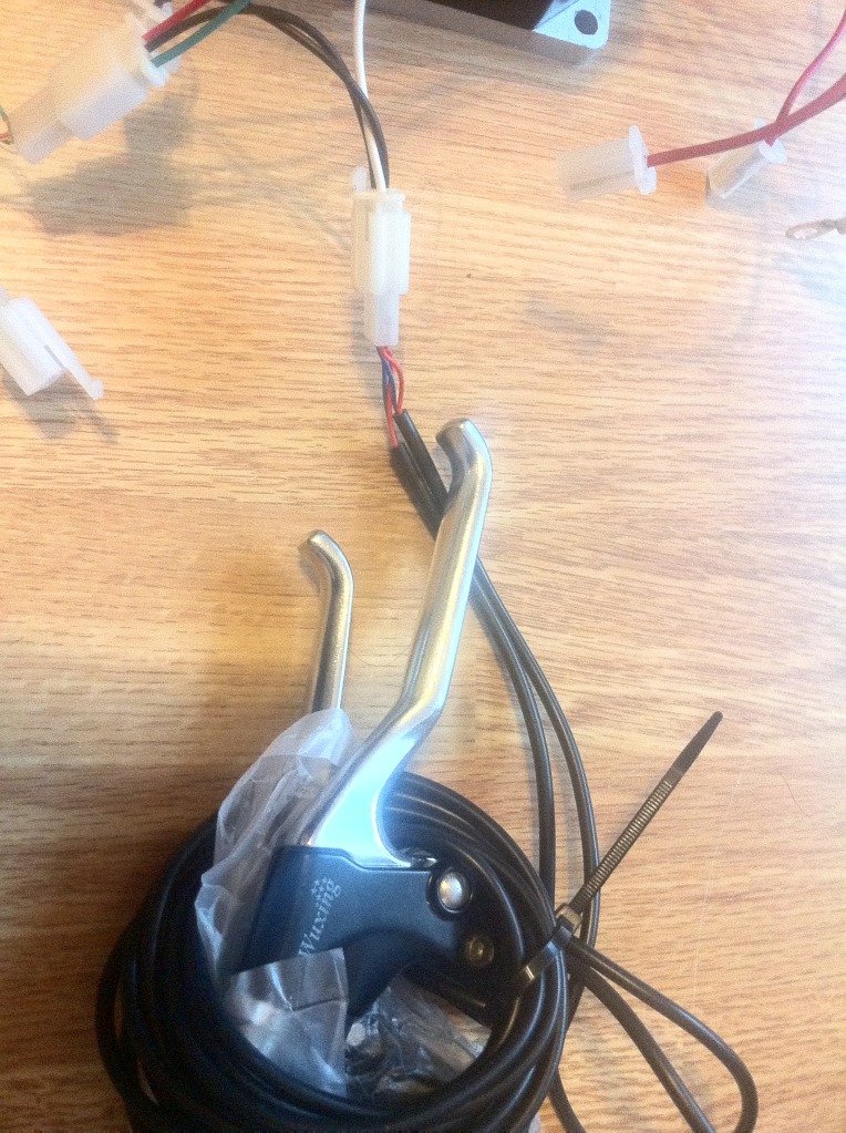
GM Twist Throttle
GM Brake Levers
Paper Clip (to substitute for not having an ignition switch on hand)
Now I am not going to show you any wiring diagrams. Just pictures of how I hooked mine up.
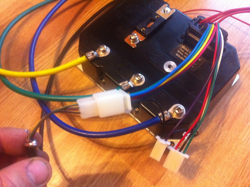
First the three phase wire from the controller to the motor like this.
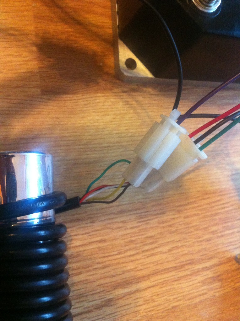
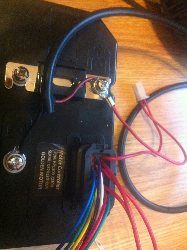
Now look at the wire harness. Please note the red wire stretched away from the rest. This is for a switch to turn on the controller.
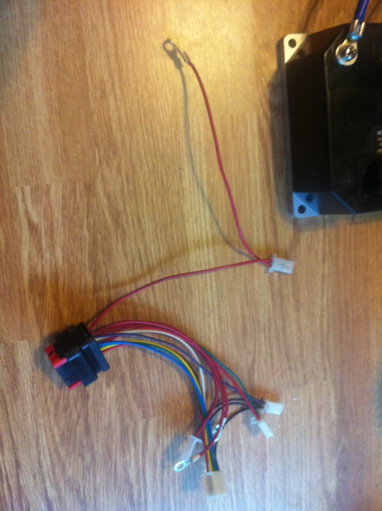
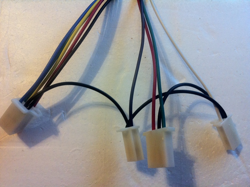
Also note the 4 other plugs from the harness. These plugs from left to right are. Hall, reverse, throttle, brake.
Now plug in the wire harness to the controller and push firmly until you hear a click sound.
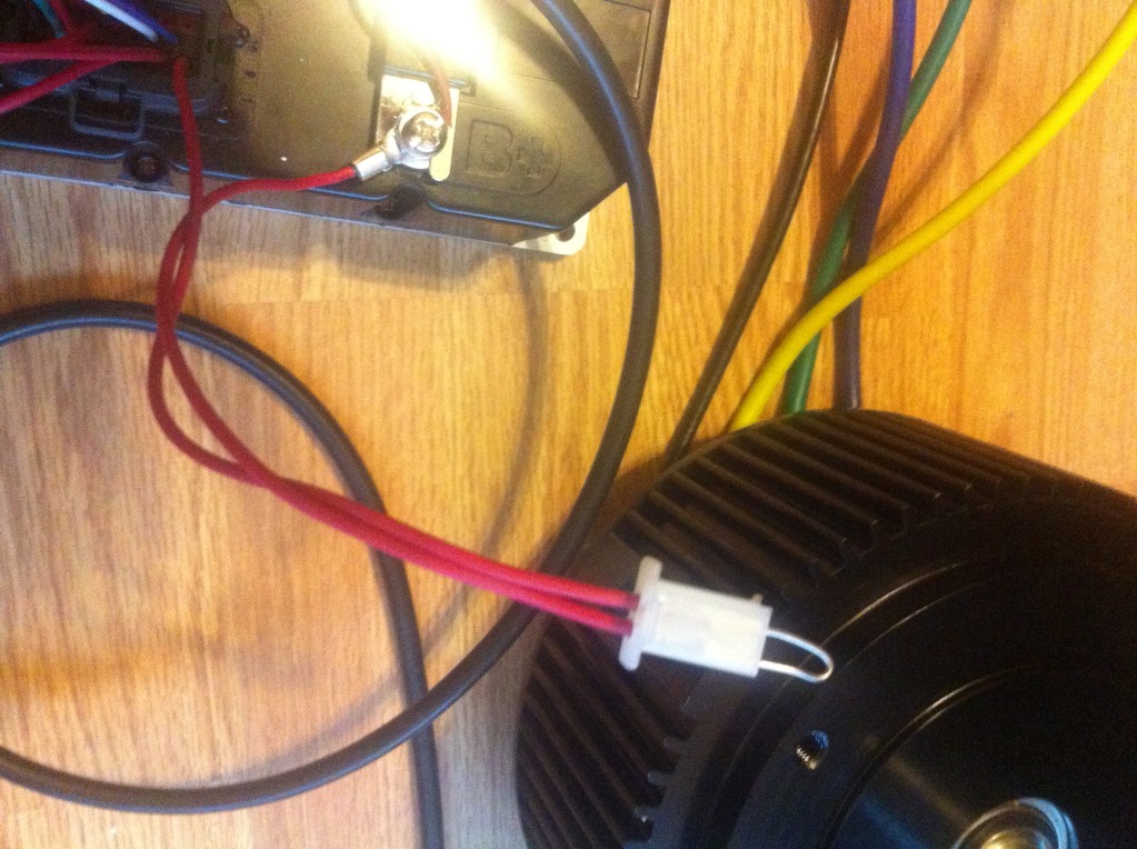
Now we take the black wire coming from the motor. It has a plug with 5 wires.
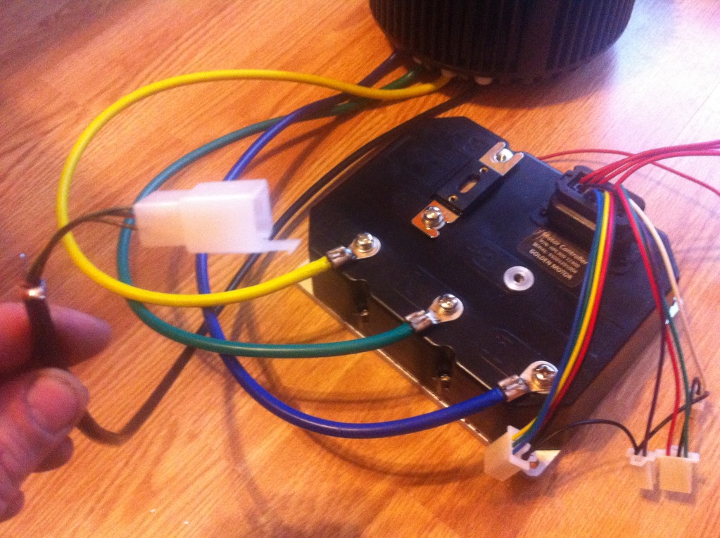
Plug it into the plug with 5 wires coming from the controller.
Next we need a Throttle. Take the plug with three wires coming from the controller.
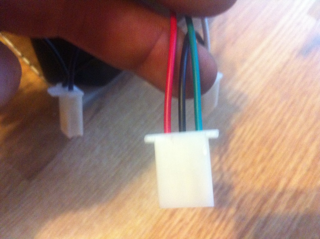
Plug it into a hand or foot throttle. In this example I am using a twist throttle.
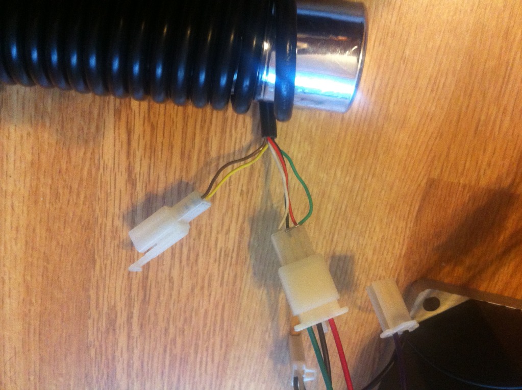
Next, look for the plug with the purple and black wires. This is for reverse.
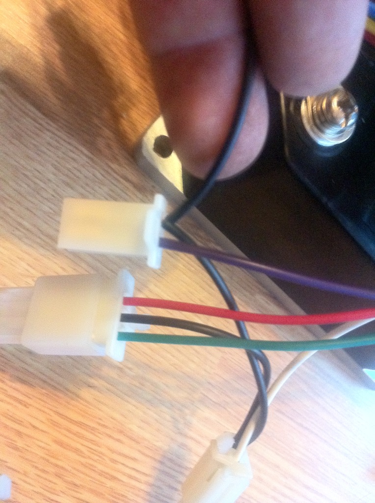
I plugged this into the 2 wire plug from the throttle. These wires are for the red button on the throttle.
Now look for the plug with the white and black wires.
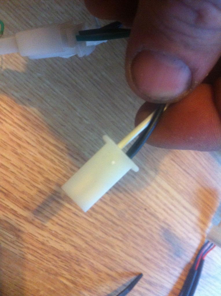
This is for the brake. For this example I used a set of power brake levers.
Next we hook up the battery.
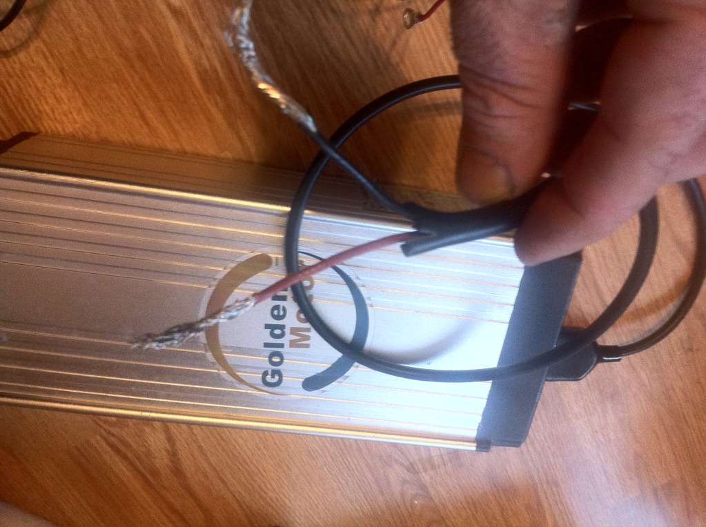
The black wire from the battery goes to the ground connection on the controller.
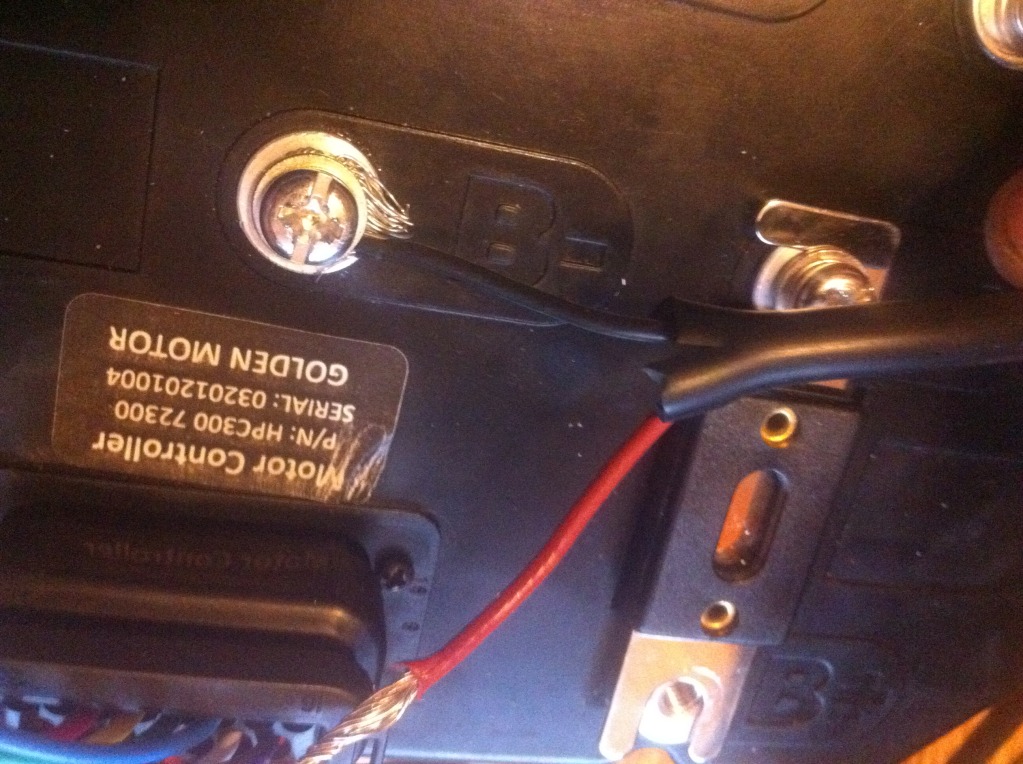
Now look for this red plug coming from the wire harness.
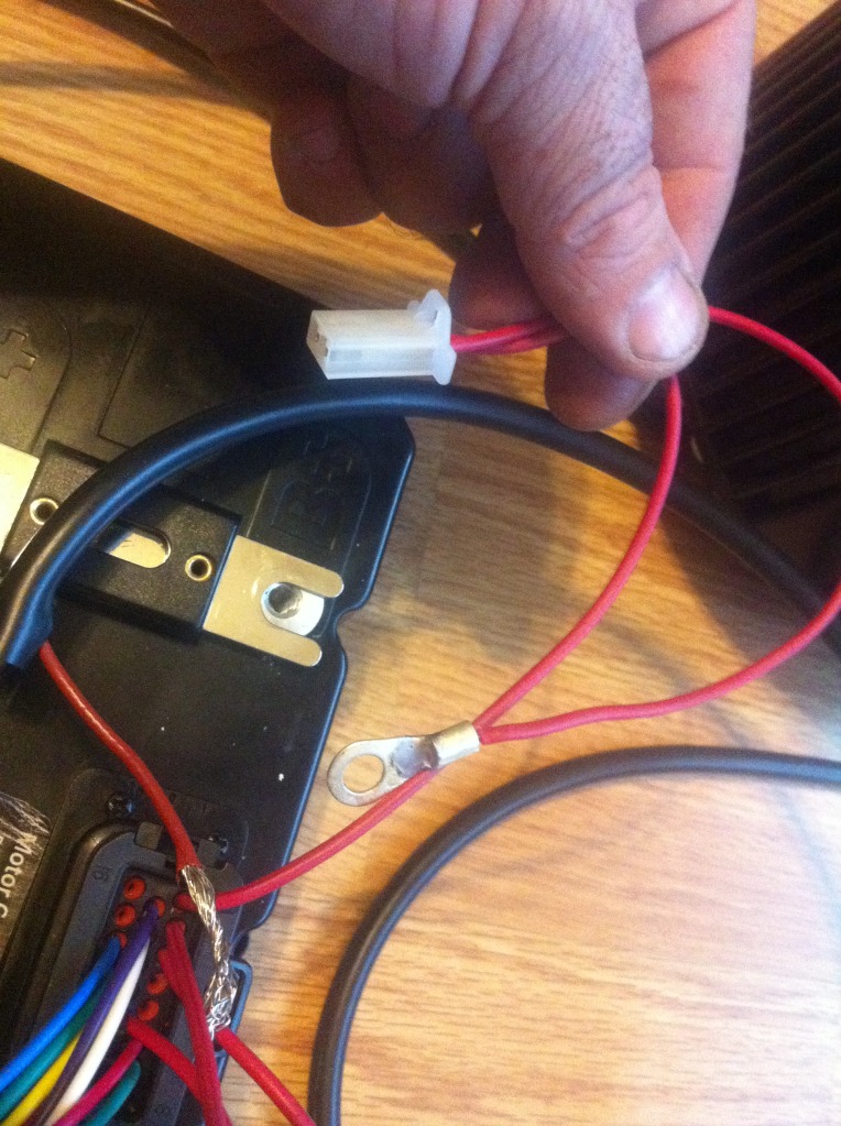
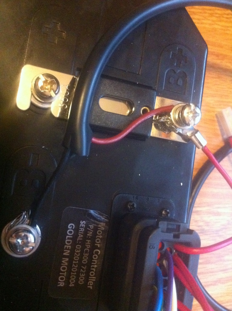
The eyelet on this red wire connects to the positive connection on the controller.
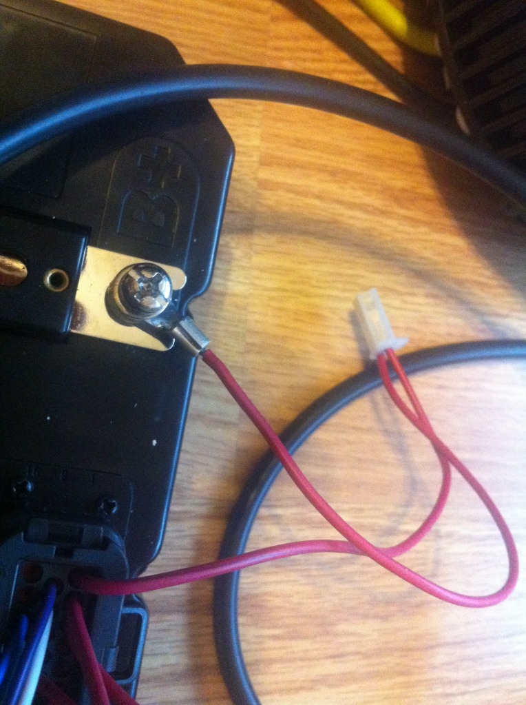
Before you tighten it down you need to also attach the red wire from the battery to the positive connection
on the controller.
Now tighten the screw down good and take this moment to go over all the screws to make sure they are
tight as well as all the plugs are connected correctly.
Now here I used a piece of a paperclip instead of a switch.
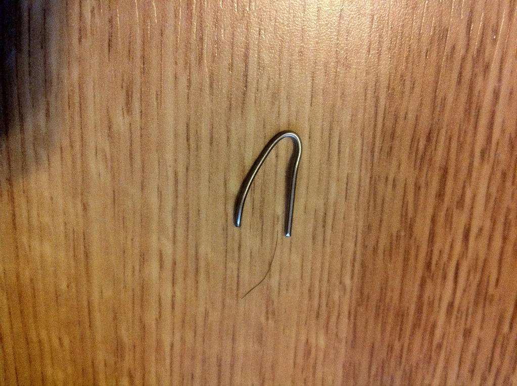
Stick it into the red plug. Normally this can be a toggle switch a key switch or any other switch. But I didn’t have one to use.
Now the wiring is complete. If you turn on the battery the red light on controller will come on. Now you can turn the throttle and the motor will spin. Let it stop , push the red button on the throttle and it will spin the other way.
When the motor is running you can use the brake levers to stop it. But be careful as the motor will go into regenerative braking mode and will spin and possibly pull the wires apart.
That’s about it. I hope this is easy enough to understand. I also created a video of this hookup for your reference.
http://www.youtube.com/watch?v=fcdjfeLGs3U&list=UUv3KWOO85wyf-opGp2gn-yA&index=1&feature=plcpGary


