Author Topic: My Magic Pie went dead (Pairing Magic pie with ecrazyman 1500w controller)  (Read 37378 times)

Offline Avantgarder

  • Confirmed
  • Magic Undergrad
  • ***
  • Posts: 66
Re: My Magic Pie went dead
« Reply #15 on: February 26, 2012, 12:38:40 PM »
Come to think of it...
The difference between the stock 20A and the 22.5A of the pussy controller is negligible...

Offline Leslie

  • Confirmed
  • PhD. Magic
  • ******
  • Posts: 2,047
Re: My Magic Pie went dead
« Reply #16 on: February 26, 2012, 02:50:35 PM »
HEHEHE Pussy controller.  :o

Agrees.   ;D

Bring it on

Offline Henry Chang

  • Confirmed
  • Junior Member
  • **
  • Posts: 44
Re: My Magic Pie went dead
« Reply #17 on: March 02, 2012, 03:14:36 PM »
Personal Suggestions, first of all your battery is full, you can go to the local distributors there, change your twist throttle, because some of the indicator light speed  at not can not be used, if it is normal and change 8 pin cable, this might not be hard line to implicate it lead to motor not turn, finally everything is normal, the problem may appear in the motor controller, changing the controller

Offline Avantgarder

  • Confirmed
  • Magic Undergrad
  • ***
  • Posts: 66
Re: My Magic Pie went dead
« Reply #18 on: March 16, 2012, 02:50:05 PM »
I have the controller from ecrazy and I'm ready to install it.
I removed the internal controller.
In order to let the cable that goes in to the motor loose, I have to remove the motor cap on the disk brake side.  Do I ?
Also ...Do I need to remove the hidden Snap-Ring in order to let the cap slide out  ?

Offline Avantgarder

  • Confirmed
  • Magic Undergrad
  • ***
  • Posts: 66
Re: My Magic Pie went dead
« Reply #19 on: March 17, 2012, 02:45:03 PM »
Anybody ? Les ? David ?

Offline Bikemad

  • Global Moderator
  • Professor
  • PhD. Magic
  • ******
  • Posts: 5,508
Re: Replacing the wires
« Reply #20 on: March 18, 2012, 01:55:29 AM »
In order to let the cable that goes in to the motor loose, I have to remove the motor cap on the disk brake side.  Do I ?
Also ...Do I need to remove the hidden Snap-Ring in order to let the cap slide out  ?


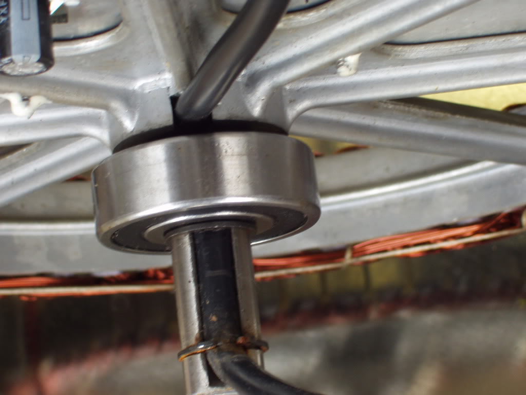
You should be able to remove the side cover first, and then remove the two circlips that are shown here:


If it doesn't release from the bearing easily, you may need to use a hammer and a wooden drift from the opposite side, to gently persuade it to let go.

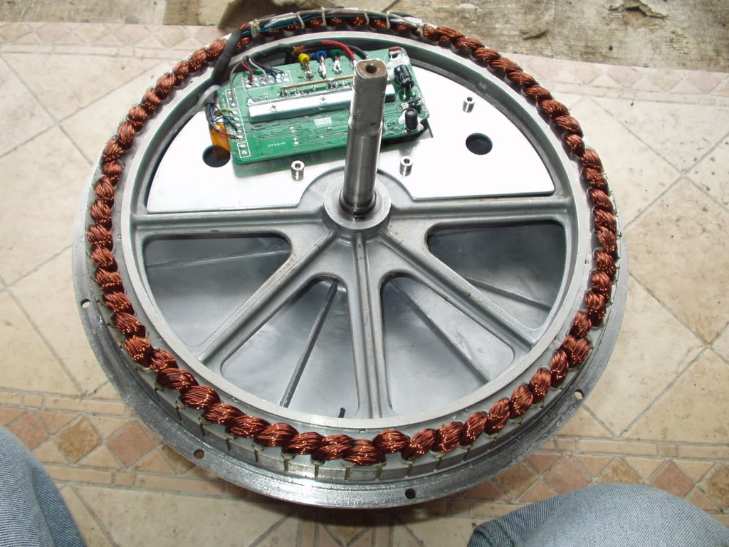
A piece of old broom handle or 1/2" dowel is ideal for this and should be positioned as close to the bearing as possible, gradually working around the eight openings in the stator to ensure the cover comes off evenly, otherwise it could tilt and jam.

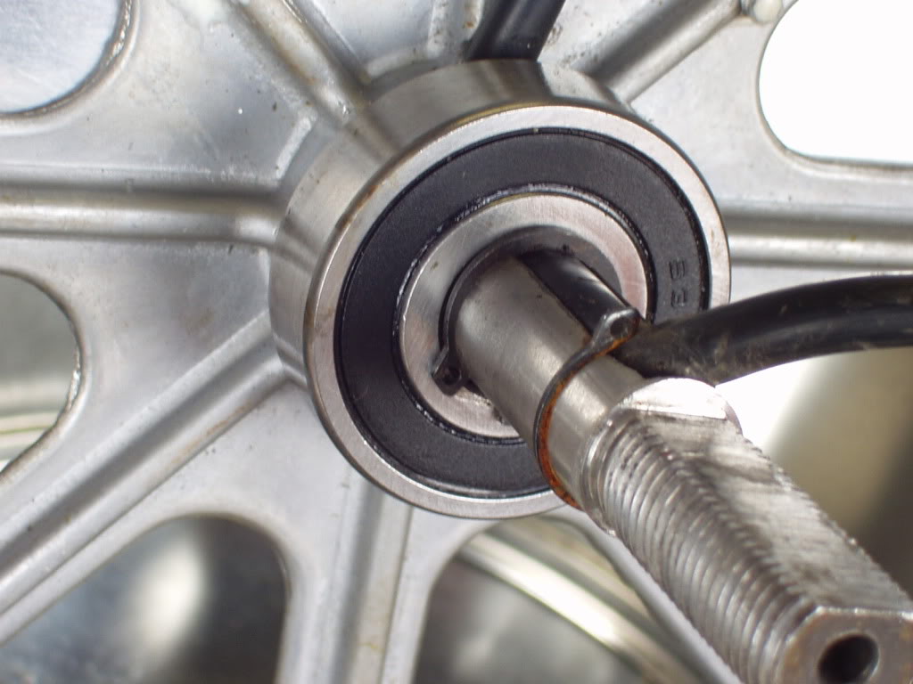
If you can slide the bearing about 1/2" away from the stator (you might need to lever it with a couple of screwdrivers or open ended spanners if it's too tight) it should make it much easier to pull the old cable through the narrow slot in the axle. Liquid soap (or silicon spray etc.) can be applied to help it slide through more easily.

With the cable removed, use a small file (or a piece of emery cloth) to remove any sharp edges from the slot before you attempt to pass the new wires through it.

You will need three lengths of heavy duty cable for the phase wires (12g EcoWireâ„¢ Plus from Alpha Wire works well for this) and five thin wires for the hall sensor connections (ribbon cable or network cable etc.).

If you use the same colour cable for all three phase leads, use a permanent marker to mark some indicator lines on both ends of the three new phase wire extension cables, so you can identify which is which when the wheel is assembled, ie G=I, B=II & Y=III.

Now you need to get all eight of these wires threaded through the slot and under the bearing with enough length to reach the wires on the stator.

Slide (or gently tap) the bearing back against the stator, and then refit the two circlips taking care not to trap any of the wires.


Solder and insulate each of the eight connections, and then make sure the wiring is secured to the stator with tie-wraps to ensure it cannot chaff against either the stator or the side covers.
Heat shrink tubing is probably the best method for insulating the soldered joints, but don't forget to slide it onto the wires as far as possible, before you solder the joints.  ;)

Fit the side cover and fixing bolts.

Fit the wheel, and then snip the wires to the required length before fitting some connectors to suit your new controller.

Alan
 
« Last Edit: July 04, 2017, 09:15:45 PM by Bikemad »

Offline Morgen 3Eman

  • Confirmed
  • PhD. Magic
  • ******
  • Posts: 620
Re: My Magic Pie went dead
« Reply #21 on: March 18, 2012, 04:20:11 AM »
Hi Alan,

Thanks for the great photos.  It really helps me to understand the construction of the MP3.

TTFN,
Dennis

Offline Morgen 3Eman

  • Confirmed
  • PhD. Magic
  • ******
  • Posts: 620
Re: My Magic Pie went dead
« Reply #22 on: March 18, 2012, 04:27:22 AM »
Hi Alan,

Since you are being so nice, could you find it in your heart to show us some photos front the other side of the motor?  To make it even easier to understand the construction?


TTFN,
Dennis

Offline Avantgarder

  • Confirmed
  • Magic Undergrad
  • ***
  • Posts: 66
Re: My Magic Pie went dead
« Reply #23 on: March 18, 2012, 09:25:33 AM »
Thanks for the pictures Alan,
I'll add some pictures from my side later today.

I actually found my own simple way to remove the motor:

1. I put a cloth on the floor and put the wheel on it with the flywheel (case already open) side of the axis facing the floor.
2. I kneel on the wheel (each knee stepping on the other edge of the tire) and gently apply pressure on the tire, one knee at a time.
3. This exotic passionate dance causes the motor to slide out in seconds.
    Apparently what was causing the difficulty to remove the motor was not the snap ring (as I thought) but the magnetic force.

I have few questions left:

1. Now that everything is out, including the old cable, I'm trying to think how would I squeeze those three 4mm^2 flexible cables I bought, through the tiny notch in the axis... This in addition to the thin haul sensor cables...
Also .... Are 4mm^2 flexible cables used for 220v thick enough for carrying 20 A ?

2. Where do I connect the 2 wires that come from the battery gauge to ?

3.  Do I connect the cable that comes from the horn (48v) and its switch directly to the battery ?

4. In the controller  document throttle = Black ; Green, Red
    In Magic Pie doc throttle = Black ; White, Red
    Does this mean  ...
    Black to Black; Green to White ; Red to Red  ?

5. The guy who sold me the motor said that 2 of of the 3 motor cables need to be crossed when connected to the controller :
    Blue->yellow
    yellow->blue
    green->green


« Last Edit: March 18, 2012, 05:51:14 PM by Avantgarder »

Offline Avantgarder

  • Confirmed
  • Magic Undergrad
  • ***
  • Posts: 66
Re: My Magic Pie went dead
« Reply #24 on: March 18, 2012, 05:53:21 PM »
I can't squeeze the cables underneath the bearing. I have to remove the bearing but I fail to do it...

Offline Morgen 3Eman

  • Confirmed
  • PhD. Magic
  • ******
  • Posts: 620
Re: My Magic Pie went dead
« Reply #25 on: March 18, 2012, 08:34:10 PM »
Hi,

If the metallic wire diameter is 4 mm it can carry about 35 amps safely.  I'm assuming your 4mm measurement does not include the insulation.   

TTFN,
Dennis

Offline Avantgarder

  • Confirmed
  • Magic Undergrad
  • ***
  • Posts: 66
Re: My Magic Pie went dead
« Reply #26 on: March 18, 2012, 10:26:26 PM »
Yes Denis. The 4mm^2 is copper only.
In fact since it's a flexible copper wire which consists of many small wires it should carry more current since it has more copper surface area. This is due to the fact that solid wires usually carry the current close to the surface area.

Offline Avantgarder

  • Confirmed
  • Magic Undergrad
  • ***
  • Posts: 66
Re: My Magic Pie went dead
« Reply #27 on: March 19, 2012, 01:03:54 PM »
More motor images...

Offline Bikemad

  • Global Moderator
  • Professor
  • PhD. Magic
  • ******
  • Posts: 5,508
Re: My Magic Pie went dead
« Reply #28 on: March 19, 2012, 01:35:12 PM »
I can't squeeze the cables underneath the bearing. I have to remove the bearing but I fail to do it...

And as for getting new wiring into the hub, yes it was a nightmare
I got 5 rolls of thin cable for the halls, and the alphawire..getting them in was fine, but I found that the circlips kept cutting into the insulation...in the end I put a couple of layers of heatshrink on the part of the circlip that holds the wires, hopefully this should suffice....all in all, with the internal controller to external controller job, I think everything that could go wrong did lol


The bearing must be centred over the slot before the cables are placed under it, as there is no way that the bearing can be fitted if the cables are already in the slot. ;)

If your intention is to remove the bearing so that you can widen the slot with a Dremel or similar, then you may need to use a bearing puller if the bearing is too tight to be levered off:


You should be able to reduce the size of the cables by carefully removing their outer insulation with a sharp knife on the portion of cable that goes through the axle and into the hub and replace it with heatshrink tubing.
This should result in a smaller diameter cable, but some heatshrink tubing has a tendency to become quite rigid, making it difficult to thread through the slot. The thinner insulation of the heat shrink will not provide anywhere near as much protection from chaffing etc., so make sure there that all sharp edges have been removed completely.


I have few questions left:

1. Now that everything is out, including the old cable, I'm trying to think how would I squeeze those three 4mm^2 flexible cables I bought, through the tiny notch in the axis... This in addition to the thin haul sensor cables...
Also .... Are 4mm^2 flexible cables used for 220v thick enough for carrying 20 A ?

You should be able to reduce the size of the cables by carefully removing their outer insulation with a sharp knife on the portion of cable that goes through the axle and into the hub and replace it with heatshrink tubing.
This should result in a smaller diameter cable, but some heatshrink tubing may make it more rigid, making it difficult to thread through the slot. The thinner insulation of the heat shrink will not provide as much protection from chaffing etc., so make sure there that all sharp edges have been removed completely.


2. Where do I connect the 2 wires that come from the battery gauge to ?

These should be connected to the battery supply cables so that the gauge comes on when the battery switch is on.

3.  Do I connect the cable that comes from the horn (48v) and its switch directly to the battery ?

Yes, just the same as the battery gauge wires above.

4. In the controller  document throttle = Black ; Green, Red
    In Magic Pie doc throttle = Black ; White, Red
    Does this mean  ...
    Black to Black; Green to White ; Red to Red  ?

Yes, Black is negative (ground), Red is +5V, and the Green or White is the variable throttle signal voltage.

5. The guy who sold me the motor said that 2 of of the 3 motor cables need to be crossed when connected to the controller :
    Blue->yellow
    yellow->blue
    green->green

Try that combination first, but if that is not correct, I think that might be a question of trial and error with different combinations using only light throttle to find the right combination.


Offline Morgen 3Eman

  • Confirmed
  • PhD. Magic
  • ******
  • Posts: 620
Re: My Magic Pie went dead
« Reply #29 on: March 19, 2012, 05:48:52 PM »
Alan, thank you for the photos.  The conversation about bearing placement and sizing makes much more sense now.  I was kind of surprised to see how nice the castings were done, and how sloppy the windings look. 

Regarding the problem with feeding wires through the axle, your wire choice is very conservative.   If the distance is kept short, smaller diameter wires can be used for quite high current loads. I have no idea what your installation looks like, but in the case of  my three wheeler,  the battery is at the front of the body, while the MP3 is at the rear, with a run of about 10 feet, so I'm using 10 AWG wire to give a voltage drop of less than a volt at 20 amp DC load.    If your controller is kept quite close to the MP,  you could get away with using 14 AWG or even smaller.  In  metric those are about 10AWG=2.5 mm, 14 AWG=1.5 mm.  You could also use the larger wire you already have to go part of the distance, and use smaller wire for threading through the axle.   It is a bad idea to select undersized connectors, tho.

TTFN,
Dennis