Author Topic: Magic Pie speed limit switch mod  (Read 6607 times)

Offline DuncanS

  • Confirmed
  • New Member
  • *
  • Posts: 2
Magic Pie speed limit switch mod
« on: November 15, 2016, 07:16:37 PM »
I would like to build the speed limiting circuit but just want to check what type of diode I should use? Signal, rectifier, schokky...if someone can point me in the correct direction that would be great.

Thanks
Duncan

Offline Bikemad

  • Global Moderator
  • Professor
  • PhD. Magic
  • ******
  • Posts: 5,510
Re: Magic Pie speed limit switch mod
« Reply #1 on: November 16, 2016, 12:27:01 PM »
Hi Duncan andto the forum.

Most common diodes (IN4001 etc.) will work as there is very little voltage or current being passed through it, but if you have an MPIII, MP4 or MP5, you don't need to use the diode, resistor and preset at all, as they are only needed for the MPII controllers.

Dan, as the Vector controller still uses the same type of throttle, the speed reducer should work just the same as on the other Magic Pies:


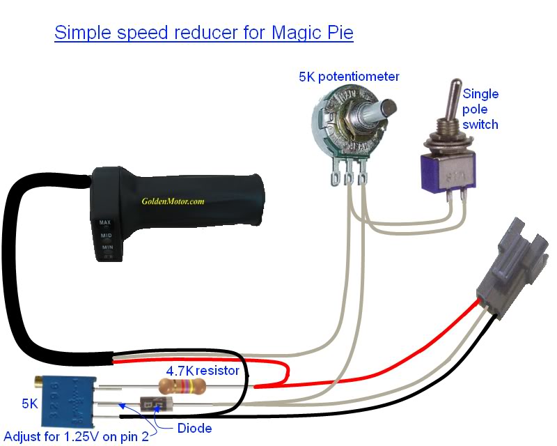
The diode and resistors in the above diagrams were needed on the Earlier Pies to prevent the controller from beeping if the signal voltage dropped too low when the throttle was fully released.
The later controllers do not have a built in audible warning device (beeper) like the original internal controllers did.

I would therefore use the more basic MPIII circuit for MP4 and MP5 controllers:


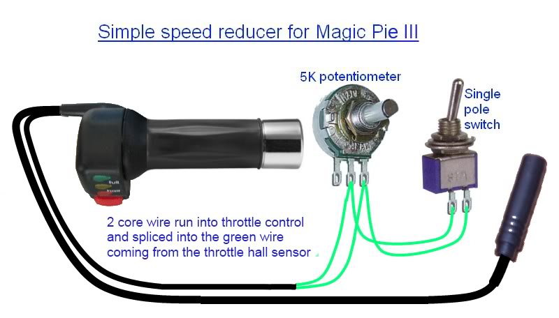
You will need to identify which colour wire is used for the throttle signal wire to ensure that you connect the speed reducer in series with the correct wire.  ;)

Check out Mike's video to see the speed reducer in action.

Please note that the wiring for the throttles can vary, therefore the throttle signal wire may not necessarily be green on your throttle.

The early style thumb throttles can be taken apart very easily to allow wires to be connected inside the throttle unit, but the twist throttles are a lot more difficult and are can become slightly damaged in the process, so splicing the additional wires into the cable might be a safer option.  ;)

Alan
« Last Edit: July 02, 2017, 11:31:42 PM by Bikemad »

Offline DuncanS

  • Confirmed
  • New Member
  • *
  • Posts: 2
Re: Magic Pie speed limit switch mod
« Reply #2 on: November 17, 2016, 09:54:26 PM »
Hi Alan,

Thanks for your detailed response and info on the diode. I had found the earlier posts about the mod searching with Google and it seemed to be the perfect solution to solve a problem I was facing. I don't have a Magic Pie, I actually have a bbs02. I used Magic Pie in the subject as that was the post I found that I wanted to ask the question on but as a new user I had to reply to the new user thread. I hope that is ok. My bss02 is my first ebike. Where I am located there really are not any suppliers of this kind of stuff and the bss02 fitted in a suitcase far easier than a 29er wheel...lol.

The problem I we looking to solve revolves round batteries and is again limited by my location and shipping lithium. I managed to source a very weak bottle battery. It 13s3p of unknown 18500 cells with a useable 250wh. As such I have the current limited to 15amps. I try and keep it around 10 apart from short bursts as it sags a fair bit. However I have managed to now source a 13s5p 17.5 Ah GA pack. So I can now up the current. However being able to use both packs would be great. Rather than having to reprogram the controller each time I was looking for a way to restrict the throttle with the smaller pack in a switched way without having to reprogram and to save accidental larger current draws on the battery.

I tried a mockup of the circuit on a breadboard using my throttle. I found that with just the 5k pot as a variable resistor the output was unaffected in terms of voltage. If I used the pot as a voltage divider I could lower the output. The only issue with that was that it would also lower the zero throttle output. Now the controller does not care, it does not report any throttle error etc. However, it does introduce a large dead band at the bottom of the throttle. Using the 2nd pot as in your m2 schematic allows that dedband to be dialed out so am very happy. I did find that I had to also put a diode on the throttle out in order to pin the minimum output to .8v.

So now I have a large battery to go fast and a smaller battery as backup/ range extension. And with the flick of. Switch I can protect the smaller battery. I can also use it to force a more economical ride and detune the bike if a friend has a go so they won't trash it.

Thanks again for your help, and enjoy your ebikes.  I would love to have a go on different motors if ever the opportunity presented itself, however not so many chances in Egypt.

Rgds
Duncan.
« Last Edit: November 17, 2016, 09:57:51 PM by DuncanS »