Author Topic: Advice wanted  (Read 4434 times)

Offline A Brinkman

  • Confirmed
  • New Member
  • *
  • Posts: 3
Advice wanted
« on: February 15, 2020, 05:15:26 PM »
Hi all, I am new to the forum. I have built 3 E-bikes last year all kits 2 of which were Bafang mid drive kits and the third a GM Magic Pie rear hub. These Kits were all plug and play and a ton of info is available for programming these controllers so up until this point my e-bike experience has been all fun and games. Recently I was recruited to repair an existing e-bike direct drive rear hub the issue appeared to be faulty wiring at the controller caused some component damage and the controller was un-responsive. My course of action to correct was upgrade to a GM magic V2 25a controller and a BAC-601 smart display seemed like a home run the motor and battery conections are straight forward and the hal sensor connection was a direct fit, Brake switches handled and I figured out the throttle and power switch connection but the display hook up is another story. Does anyone out there have experience using these parts together. The Chat guy on the GM site said they were compatible and the controller would be programable from the display, but I cant find any usefull info on the net. Any help is greatly appreciated.

Offline Bikemad

  • Global Moderator
  • Professor
  • PhD. Magic
  • ******
  • Posts: 5,497
Re: Advice wanted
« Reply #1 on: February 16, 2020, 12:27:48 AM »
Hi andto the forum.

Does anyone out there have experience using these parts together. The Chat guy on the GM site said they were compatible and the controller would be programable from the display, but I cant find any usefull info on the net.

The Chat guy on the GM site obviously requires a bit more product knowledge, because the BAC-601 Smart LCD display unit is only suitable for use with Magic Pies and Smart Pies with Vector controllers:


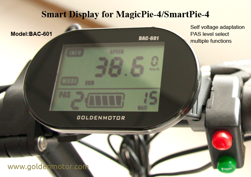
There are actually different versions of the BAC-601 Smart LCD display, one suitable for the MP4 and SP4 and another for use with MP Edge, MP5 and SP5.

The BAC-28XP controller should work fine with your direct drive hub, however, the Smart LCD display is not going to work with a BAC-28XP cruise speed controller:


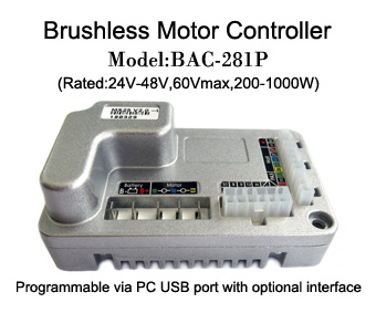
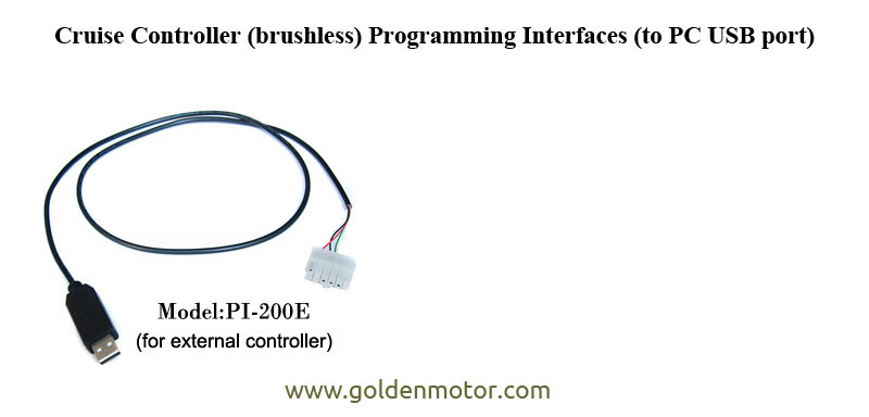
Even if it did work with the BAC-28XP controller, you would still not be able to adjust any of the controller's programmable parameters using the BAC-601 Display unit. You would need the PI-200E USB programming cable connected to a Windows PC/laptop running the Cruise Controller Parameter Setting Software:


I realise this is probably not be what you wanted to hear, but what you are trying to do is simply not going to work.   :(

Alan
 

Offline A Brinkman

  • Confirmed
  • New Member
  • *
  • Posts: 3
Re: Advice wanted
« Reply #2 on: February 16, 2020, 05:55:42 PM »
your right not what I wanted to hear :( but thank you for your help.  Do you know how the 5 conductor cable for the BAC 601 pins out per wire color ? red, black, blue, yellow, green im sure its +5v, -5v, Tx, and Rx with a spare but not sure which color does which   :-\

thanks
« Last Edit: February 16, 2020, 07:39:08 PM by A Brinkman »

Offline Tommycat

  • Confirmed
  • Bachelor of Magic
  • ****
  • Posts: 178
Re: Advice wanted
« Reply #3 on: February 16, 2020, 07:55:45 PM »
Not by wire color...  but if it had the original Higo connector as used with a Magic Pie Vector controller, this might help... See 5 pin connector on motor harness side.


For a bit of color, here is the wiring as it leaves a Vector controller...


I don't know if they would carry on the wire coloring to the rest of the harness or not...
But I personally would never trust any wiring as per color... If I had to, I would try to open up the display, and trace the wiring to the PCB where they're hopefully labeled.


Regards,
T.C.
See my completed Magic Pie V5 rear hub E-Bike build  HERE.

Offline Bikemad

  • Global Moderator
  • Professor
  • PhD. Magic
  • ******
  • Posts: 5,497
Re: Advice wanted
« Reply #4 on: February 17, 2020, 12:01:14 AM »
If I had to, I would try to open up the display, and trace the wiring to the PCB where they're hopefully labeled.

If you still have the original plug (assuming you have already chopped it off to access the individual wires) you may be able to trace the wire colours to the individual pins using a continuity tester on the remaining bits of wires to determine which colour connects to each pin on the appropriate wiring diagram.
The MP5 diagram is shown in Tommycat's previous post and the MP4 wiring diagram is shown here:


The only difference I could find between the wiring of the MP4 and MP5 motor harnesses was pin 4 on the 5 pin connector, as the +5V supply was not present on the MP4 Motor harness that I tested when I originally drew the MP4/SP4 diagram.

Make sure that you mirror the connections when testing the pin end of the BAC-601 connector, as the connector view in the diagram is from the pin side of the controller's connector, not the connector on the LCD display or USB programming cable. The Bluetooth dongle did not work with the MP4 controllers (perhaps it just needs the +5V supply to power the dongle).

I still don't think you will get it to work properly as the MP4 and MP5 both use a different communication interface and programming software to the  BAC-28XP and MPIII controller, and presumably a different communication protocol too. :-\

Alan