Author Topic: 3kw bldc motor and controller issue  (Read 15339 times)

Offline Mechanic

  • Confirmed
  • New Member
  • *
  • Posts: 17
3kw bldc motor and controller issue
« on: May 25, 2016, 04:53:23 PM »
I got a 48v 3kw bldc motor and controller from goldenmotor.ca. I've hooked everything up as per the diagram. I have 48v across the controller fuse and controller ground. I am getting no response from the throttle. I unplugged the throttle and checked the wires from the controller and there is 0v on any of them, anyone have any ideas?

Offline Rayhaque

  • Confirmed
  • New Member
  • *
  • Posts: 16
    • My Zap Urbee Sightseeing Thing Blog
Re: 3kw bldc motor and controller issue
« Reply #1 on: May 26, 2016, 03:10:11 PM »
Hello Mechanic,

What is your "e-lock" connected to? It should be provided with 48v which in the case of a car would come from an ignition. But if you have no lock, or ignition, you need to connect it directly to the 48v+ connection on the controller. Seems simple enough, but that threw me for a loop when I was hooking up my GM gear.

Offline Mechanic

  • Confirmed
  • New Member
  • *
  • Posts: 17
Re: 3kw bldc motor and controller issue
« Reply #2 on: May 26, 2016, 05:43:56 PM »
Ok I assumed if that if you didn't want to use that feature you leave it unhooked. I'll try that when I get back to work and see what that does. Too bad these controllers don't come with some sort of  instructions or documentation!

Offline Mechanic

  • Confirmed
  • New Member
  • *
  • Posts: 17
Re: 3kw bldc motor and controller issue
« Reply #3 on: May 26, 2016, 05:49:05 PM »
Tried putting the elock straight to 48v, still no 5v to the throttle wire...

Offline Rayhaque

  • Confirmed
  • New Member
  • *
  • Posts: 16
    • My Zap Urbee Sightseeing Thing Blog
Re: 3kw bldc motor and controller issue
« Reply #4 on: May 27, 2016, 11:36:26 AM »
Too bad these controllers don't come with some sort of  instructions or documentation!
I am fighting that myself. I am having trouble with my 5Kw/72v motor and controller from GM. And I can't help but think it's a matter of getting the settings right on the controller. But it's not like they have technical support ... or even a manual. Just some broken English to explain about a third of the settings when you hover over them with the programming software.

Speaking of programming software - what model controller do you have?  Is it the VEC200? I have the VEC300 myself and although I bought it as a 72v, it can actually do 48v and 60v (but defaults to 72v out of the box). I would think that the one you have is defaulted to 48v since you bought it that way. But there really isn't any way of telling that I know of.

These controllers need some sort of diagnostics!!! A flashing light. A bleeping siren. Some sort of output!

Offline Mechanic

  • Confirmed
  • New Member
  • *
  • Posts: 17
Re: 3kw bldc motor and controller issue
« Reply #5 on: May 27, 2016, 09:28:12 PM »
Its the vec200. I used the wiring diagram they provide on the website. The controller looks different but the wire colors are the same.

Offline Mechanic

  • Confirmed
  • New Member
  • *
  • Posts: 17
Re: 3kw bldc motor and controller issue
« Reply #6 on: May 27, 2016, 09:29:47 PM »
I thought maybe I was supposed to buy the flash connecter and set it up to make it work but according to the seller it should work out of the box...

Offline Mechanic

  • Confirmed
  • New Member
  • *
  • Posts: 17
Re: 3kw bldc motor and controller issue
« Reply #7 on: May 30, 2016, 11:42:33 PM »
So I realized that when I hooked that red e-lock wire up I was hooking it to nothing, I hooked the pink to 48v and now the 5v reference appears but still no motor operation. I checked the output wire from the throttle and its 0.0v. This is a twist throttle from golden motor. I just matched the colors up, maybe that's not right? I tried running a resistor from 5v to the green signal and there's a red light on the controller that flashes 12 times then repeats, anybody know what that means?

Offline GM Canada

  • Super Gary
  • Confirmed
  • PhD. Magic
  • ******
  • Posts: 1,544
Re: 3kw bldc motor and controller issue
« Reply #8 on: June 01, 2016, 02:18:54 PM »
Hi Mechanic, I finally found my way here. Whew have I been down wit the flu!

If you now have 5 volts going into the throttle and nothing coming out its either wired wrong or failed. Can you upload a picture of the wiring connection?

Gary


Offline Mechanic

  • Confirmed
  • New Member
  • *
  • Posts: 17
Re: 3kw bldc motor and controller issue
« Reply #9 on: June 02, 2016, 01:48:30 PM »
Throttle
« Last Edit: June 02, 2016, 01:58:40 PM by Mechanic »

Offline Mechanic

  • Confirmed
  • New Member
  • *
  • Posts: 17
Re: 3kw bldc motor and controller issue
« Reply #10 on: June 02, 2016, 02:01:40 PM »
Maybe this one is better

Offline Mechanic

  • Confirmed
  • New Member
  • *
  • Posts: 17
Re: 3kw bldc motor and controller issue
« Reply #11 on: June 02, 2016, 02:04:27 PM »
The white is going to 48v

Offline Bikemad

  • Global Moderator
  • Professor
  • PhD. Magic
  • ******
  • Posts: 5,502
Re: 3kw bldc motor and controller issue
« Reply #12 on: June 02, 2016, 04:02:08 PM »
It is very unlikely that the colour codes used on all throttle will be the same and you don't mention which throttle you are using.

The last GM thumb throttle that I took apart was wired differently to yours:

White: +5V
Black:  Battery -ve (Ground)
Green: Throttle Signal
Orange:     Battery +ve feed for LED battery gauge and lighting switch
Brown:  Switched Lighting feed (battery voltage)


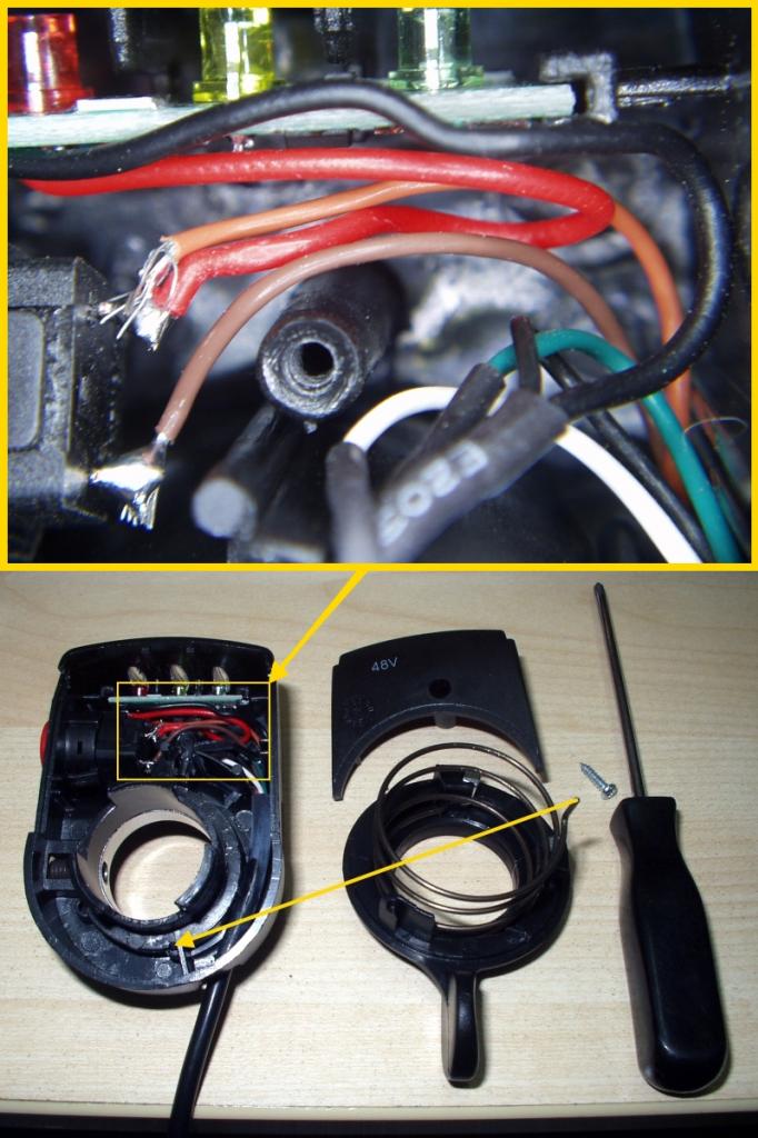
On the thumb throttle below, the green wire is used to supply battery voltage to the LED battery gauge:


The red wire connected to the battery gauge PCB in the above picture is actually battery -ve!  ???
(It simply connects the Ground connection on the PCB to the black ground wire going to the Hall sensor)

Earlier twist throttles were also wired differently as follows:
Red:   +5V
Black:  Battery -ve (Ground)
White: Throttle Signal
Green: Battery +ve feed For LED battery gauge
Brown: Lighting or reverse switch
Yellow: Lighting or reverse switch


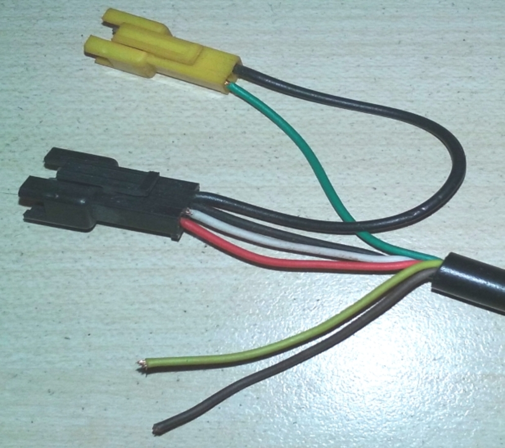
Did your throttle come with the correct connections for your controller already fitted?

If the throttle was not pre-wired to match the controller and you don't know what each colour wire on the throttle is for, it would be very unwise to simply connect them to together by colour alone, as this could result in a damaged throttle unit or even a damaged controller.  :o

Can you visually check the connections inside the throttle to be able to determine the function of each wire?

Alan
 
EDIT: Additional photos added
« Last Edit: July 04, 2017, 09:23:19 PM by Bikemad »

Offline Mechanic

  • Confirmed
  • New Member
  • *
  • Posts: 17
Re: 3kw bldc motor and controller issue
« Reply #13 on: June 03, 2016, 08:58:22 PM »
Oh I see, I assumed the throttle from golden motor would match their controller. It sounds like mine is the earlier version you talk about. I did verify the yellow and brown was the switch. If this is the case then I guess i'd have the green and white reversed...

Offline Bikemad

  • Global Moderator
  • Professor
  • PhD. Magic
  • ******
  • Posts: 5,502
Re: 3kw bldc motor and controller issue
« Reply #14 on: June 04, 2016, 11:18:29 AM »
I have added a few more pictures to my previous post showing the wiring connections on two different GM throttles, both of them use the white wire for the Hall sensor output signal.

The white is going to 48v

If you have fed 48V+ to the throttle Hall sensor signal connection, there's a good chance that the Hall sensor may have been damaged by the high voltage.  :(


                   Click image to view the original thread.                   


As the +5V feed on the controller is still working OK, I suspect the controller will still be OK.   :)
Although I'm not so optimistic about the Hall sensor inside the throttle.  :-\


Alan
 
« Last Edit: July 02, 2017, 04:22:12 PM by Bikemad »