In my case from left to right there are green, blue, yellow.
lets say green is 1, blue is 2 and yellow is 3
now you have three wires called 1,2,3 and on the other you have 1a,2a,3a
connect in this order :
1 - 2a
2 - 3a
3 - 1a
Now I'm confused

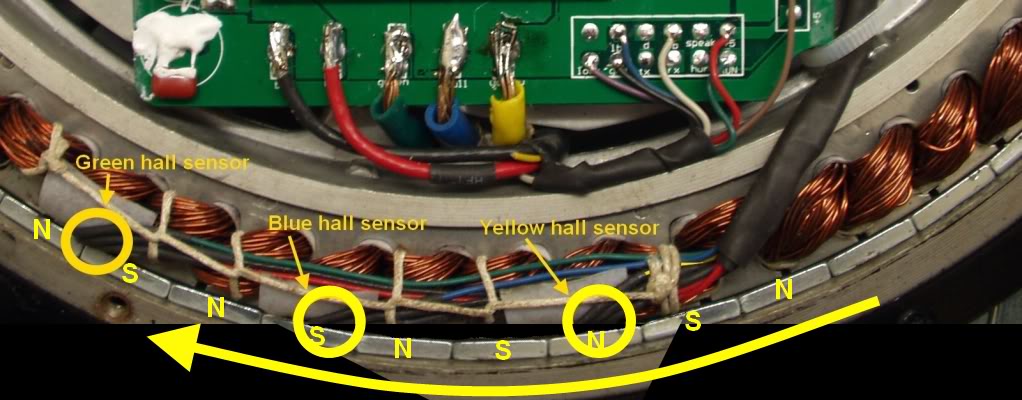
in my original diagram, I presumed that the phase order was "Yellow - Blue - Green", because this is the order in which the magnets pass the hall sensors on my Pie when the wheel is turned in a forward direction:

That would mean that:
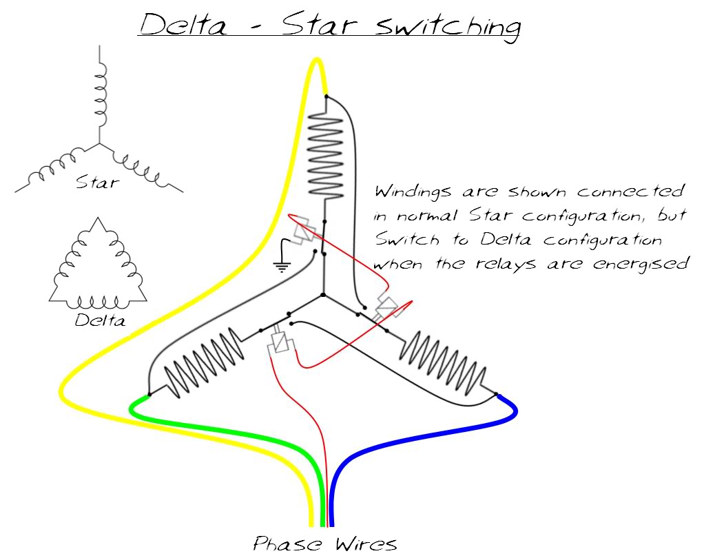
The Yellow phase lead connects to the switched end of the Blue windings
The Blue phase lead connects to the switched end of the Green windings
The Green phase lead connects to the switched end of the Yellow windings
As shown in my original diagram here:

But you say that you've connected your leads like this:
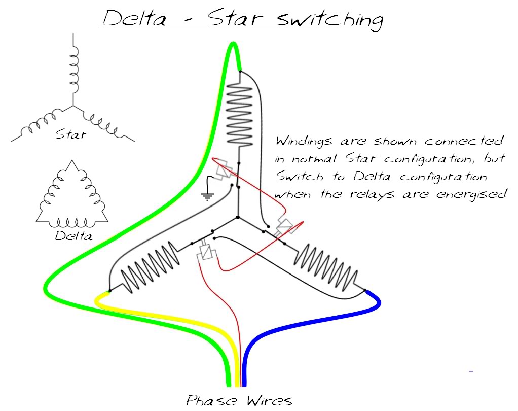
The Green phase lead connects to the switched end of the Blue windings
The Blue phase lead connects to the switched end of the Yellow windings
The Yellow phase lead connects to the switched end of the Green windings
As per this modified diagram:

Now I'm not sure which one of the above diagrams is actually correct for the Magic Pie.
Either I've got the phase order wrong, or your pie is different to mine, but I'm not sure how can we find out for sure which of the above diagrams is correct, unless you want to pull your hub apart again and try changing your connections and see what happens?
 Alan
Alan